
Apparatus for Field-Flow Fractionation

a technology of apparatus and flow rate, applied in the field of apparatus for fieldflow fractionation, can solve the problems of limited dynamic region of flow rate, limited range of working pressure in which mass flow regulators may be used, delay in response time for flow rate control, etc., and achieve the effects of reducing cost and risk of failure, reducing cost and risk

Inactive Publication Date: 2016-01-14
POSTNOVA ANALYTICS
View PDF5 Cites 15 Cited by
  • Summary
  • Abstract
  • Description
  • Claims
  • Application Information

AI Technical Summary

Benefits of technology

The patent describes a new method for separating samples using a programmable focus flow. This method uses sequential splitting of the flows by valves, which eliminates the need for mass flow regulators. This reduces the cost and risk of failure. The method also improves sample recovery and prevents aggregate formation. Overall, this method simplifies the design and reduces the risk of failure.

Problems solved by technology

The technical problem addressed in this patent is how to improve the analysis of samples using field-flow fractionation techniques by controlling the flow of solvent and reducing pressure variation during the process.

Method used


Image

  • Apparatus for Field-Flow Fractionation
  • Apparatus for Field-Flow Fractionation
  • Apparatus for Field-Flow Fractionation

Examples


Embodiment Construction

[0126]In the following, preferred embodiments of the apparatuses of the invention will be explained with reference to the attached drawings and the reference numerals used there.

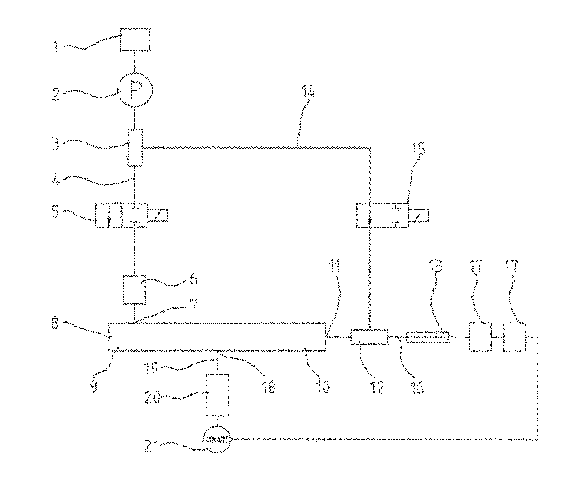
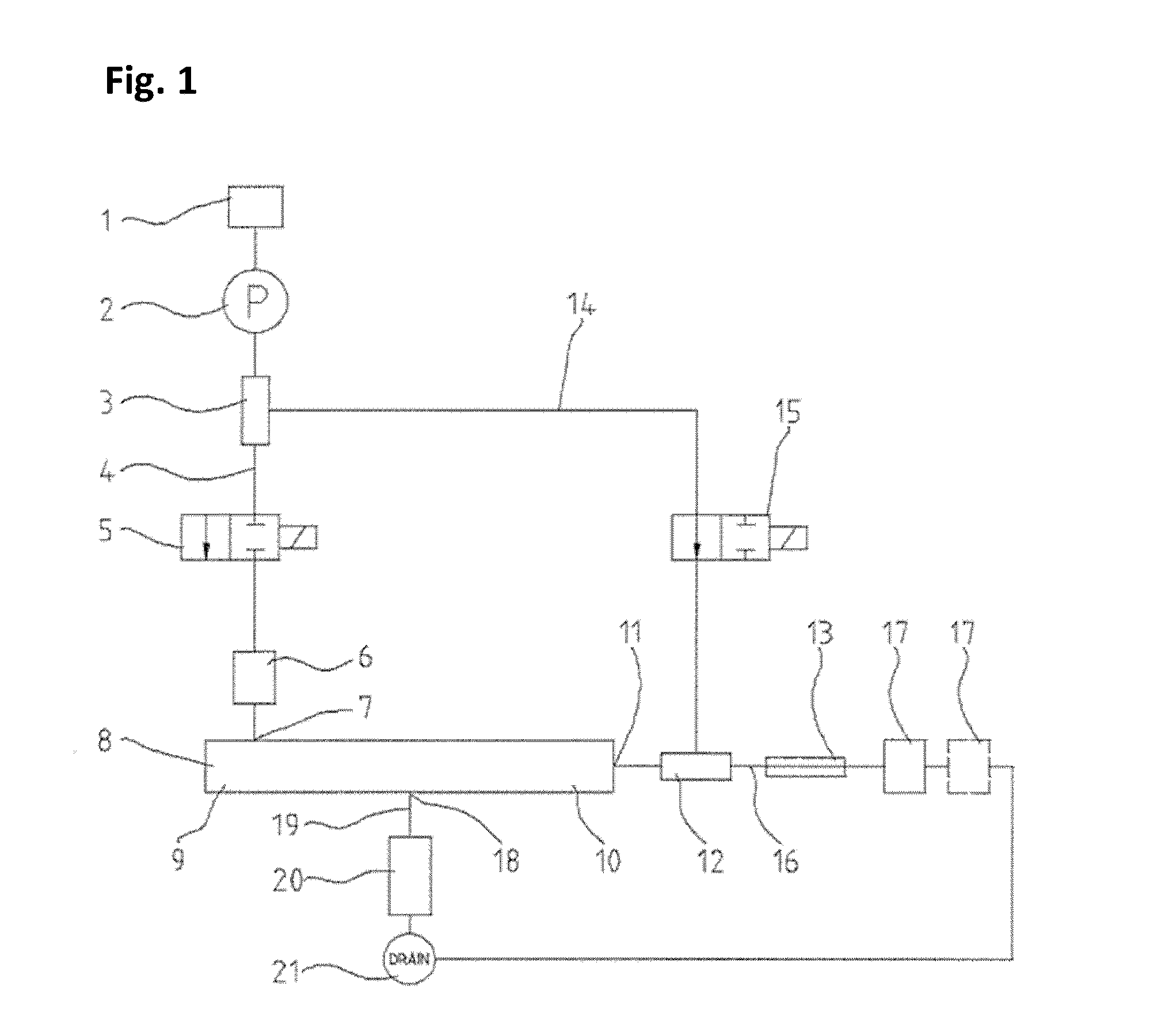
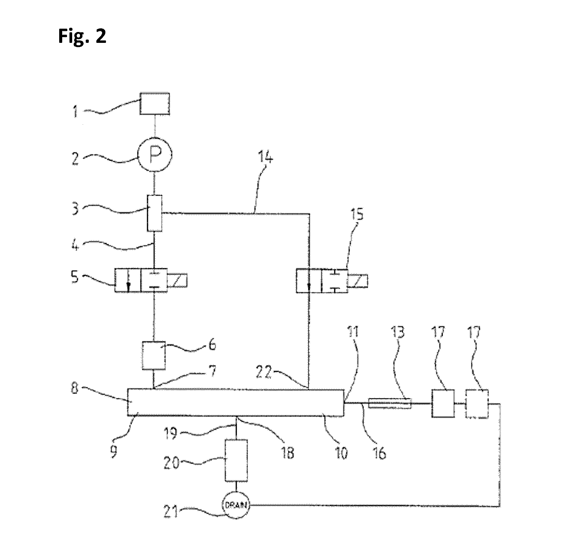
[0127]FIG. 1 shows the schematic design of an apparatus for field-flow fractionation according to the invention. Having passed a reservoir (1) and a pump (2), the volume flow is split via a T-connector (3) into a first flow path (4) and a second flow path (14). The first flow path (4) is initially guided to a first valve (5) and then, via an injector (6), to a first connector (inlet) (7) at a first end (9) of the separation channel (8). The separation channel can either be a hollow-fiber separation channel or an AF4 separation channel.

[0128]The second flow path (14) is guided to a second T-connector (12) via a second valve (15). This T-connector splits the volume flow between a second connector (outlet) (11) at a second end (10) of the separation channel (8) and a third flow path (16) which is guided to the ...


PUM


Abstract

The present invention relates to an apparatus for field-flow fractionation and to a method for separating samples by means of field-flow fractionation using this apparatus. The apparatuses of the invention comprise one or more reservoirs, a pump, a first flow volume splitting device, two valves for flow control, an injector, a separation channel having a first connector at a first end and a second connector at a second end or an AF4 separation channel having a first connector at a first end, a second connector at a second end and a third connector between the first and the second ends, optionally a second flow volume splitting device, a back-pressure element, one or more detector(s), a flow volume control device and one or more waste container(s). The apparatuses of the invention are characterized in that they comprise a valve for flow control in a first flow path and a second flow path which connect the pump to the first or the second or the third connector of the separation channel and that these valves are switched alternately in a controllable time ratio.

Description


Claims


Application Information

Patent Timeline
Owner POSTNOVA ANALYTICS
Learn More