Valve body of a dosing device

a technology of detergent dosing device and valve body, which is applied in the direction of valve operating means/releasing devices, carpet cleaners, cleaning equipments, etc., can solve the problems of unsatisfactory methods, poor versatility, and complex of current detergent dosing devices, and achieves the effect of reducing maintenance costs, facilitating replacement and simplifying inspection and maintenan

Active Publication Date: 2016-01-21
TTS CLEANING SRL
View PDF3 Cites 7 Cited by
  • Summary
  • Abstract
  • Description
  • Claims
  • Application Information

AI Technical Summary

Benefits of technology

[0035]Advantageously the seal for closing the outlet pipe is, during closing, subject to the pressure ofn the lower part of the first element of the valve body that pushes from the outside of the hollow body.
[0036]Advantageously the seal for closing the outlet pipe is on the closing edge of the outlet pipe.
[0037]Advantageously said first element of the valve body can be extracted from within the hollow body through the outlet pipe for its maintenance and / or its replacement.
[0038]Advantageously at least one of said seals is joined solidly to the upper and / or lower element of the valve body, remaining exposed and protruding during at least one of the pre-set positions so that it can be easily replaced.
[0039]Alternatively to the advantage previously set out, at least one of said seals is connected solidly to the mouth of the opening of the inlet pipe and / or outlet pipe, held inside a specific housing, remaining securely sheltered when the device is operating.
[0040]Said first lower element and said second upper element connect, supporting directly or entering into contact following the movement with the relative seals for closing the outlet and inlet pipes; in both modes of installing the seals, because of their arrangement, the inspection and maintenance of the seals are considerably simplified, since the seal on top of the second element is near the inlet mouth and the seal below the first element is near the outlet mouth.

Problems solved by technology

In the past there have been attempts to pursue these aims with equipment that in many ways have proven to be unsatisfactory.
In fact, the complexity and poor versatility of the current detergent dosing devices is well known, which include a top tank that is joined to a dosing chamber underneath, inside which there is a valve operated by actuating devices controlled by the operator, to release the liquid stored inside the chamber itself, into a basin underneath.
These and other examples of previous dosing devices for releasing a pre-set amount of detergent, have proven to be poorly accepted by professional operators because of their inherent drawbacks.
One of the main drawbacks of current dosing devices concerns the difficult maintenance and the replacement of worn parts, with lengthy periods of time required for carrying out the above-mentioned operations.
Moreover, these very dosing devices have evident operational difficulty, because the operator has to, with each change of the detergent, go to a specific area and discharge / empty out all the detergent, even that in the tank, in order to then fill the tank and use a fresh and different type of detergent.

Method used


Image

  • Valve body of a dosing device
  • Valve body of a dosing device
  • Valve body of a dosing device

Examples


Embodiment Construction

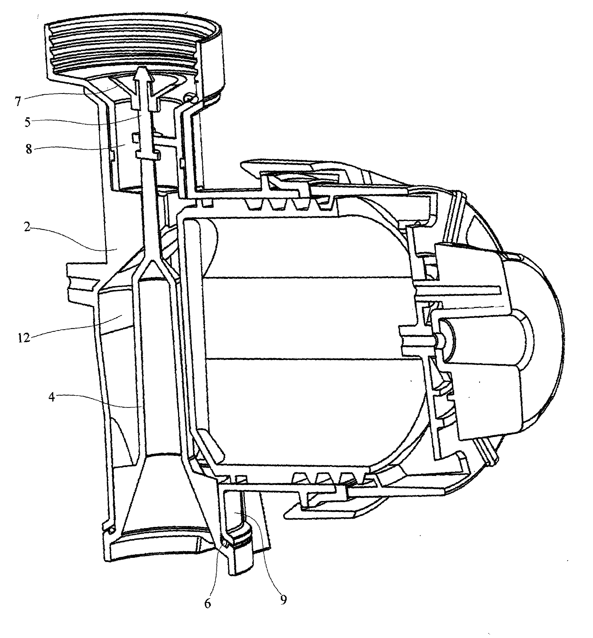
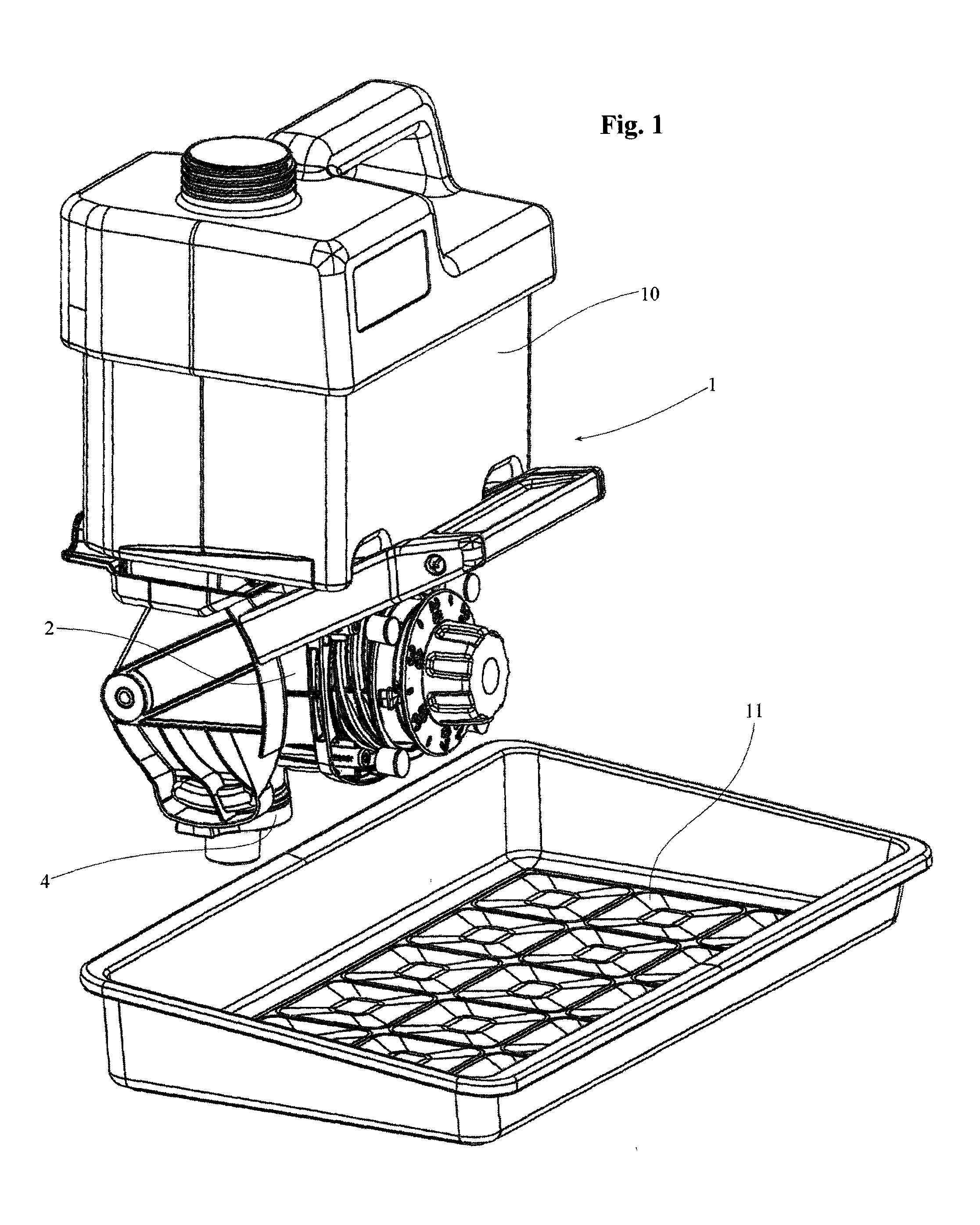
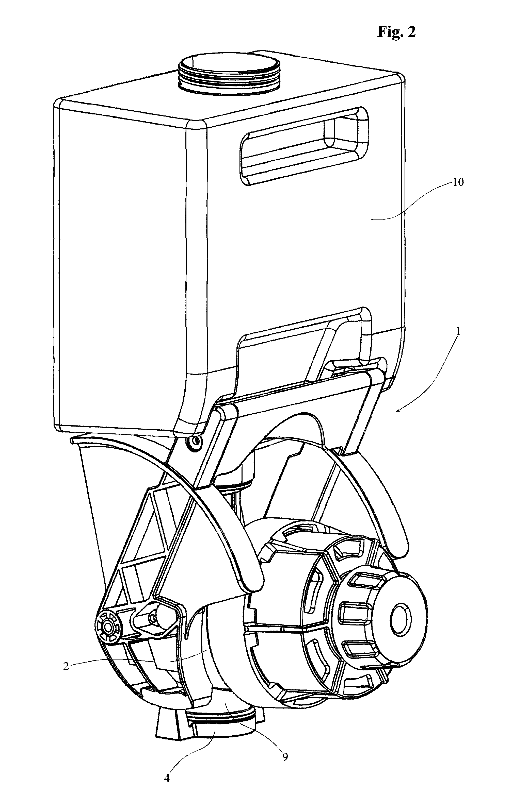
[0065]On top of the dosing device 1 there is a tank 10 communicating hydraulically with the hollow body 2 beneath, from which is released the detergent stored in its dosage volume 12, into a soaking basin 11 underneath.

[0066]The inlet 8 and outlet 9 pipes of the hollow body 2 are opened and closed by a float valve 3 inside said hollow body 2.

[0067]In a first preferred and not limiting realisation of the valve body 3, it has two individual elements 4, 5 floating in the hollow body 2, with a possibility of their limited movement along its main axis.

[0068]The first element 4 of the valve body 3 is lower down and has a tubular configuration, preferably conical or truncated-conical; said first element 4 near the lower base has a hydraulic seal 6 for sealing the outlet pipe 9, or closing pipe, of the hollow body 2, in a first raised position explained above.

[0069]In this configuration, said first element 4, on the bottom, pushes with its top end the second element 5 of the valve body 3, o...


PUM


Abstract

The object of this invention is a valve body of a cleaning appliance, specifically a dosing device, whose valve body can open and close the inlet and outlet pipes of the dosing chamber of said dosing device, to release a correct amount of detergent for soaking a cleaning cloth.

Description

CROSS-REFERENCE TO RELATED APPLICATIONS[0001]This application claims the benefit of PCT Patent Application PCT / IB2014 / 059205, filed on Feb. 14, 2014 and Italian Patent Application PD2013 / A000041, filed on Feb. 25, 2013, both incorporated herein by reference.STATEMENT REGARDING FEDERALLY SPONSORED RESEARCH AND DEVELOPMENT[0002]Not Applicable.FIELD OF THE INVENTION[0003]The field of application of the invention concerns a valve body of a cleaning appliance, specifically a dosing device, whose valve body can open and close the inlet and outlet pipes of the dosing chamber of said dosing device, to release the right amount of detergent for soaking a cleaning cloth.DISCUSSION OF RELATED ART[0004]It is well known that all appliances in the professional sector have to meet higher levels of quality than those to be used in a domestic setting.[0005]This quality level refers both to the construction material as well as to the relative design, so that said appliances are durable and easy to use...

Claims


Application Information

Patent Timeline
Patent Type & Authority Applications(United States)
IPC IPC(8): A47L13/50B67D3/00F16K31/528G01F11/32
CPCA47L13/50B67D3/0045G01F11/32F16K31/528
Inventor ZORZO, RENATO
Owner TTS CLEANING SRL
Why Eureka
Try Eureka