
Fluid throttle member

Inactive Publication Date: 2016-01-21
KYB CORP
View PDF3 Cites 3 Cited by
  • Summary
  • Abstract
  • Description
  • Claims
  • Application Information

AI Technical Summary

Benefits of technology

The technical effect of this patent is to reduce the variation in the flow area of a throttle hole in a fluid throttle member.

Problems solved by technology

However, in such an orifice pin, the injection hole is deformed by stress generated at the time of press-fitting into the orifice pin insertion hole.
Therefore, there is a fear that variation in a flow passage area of the injection hole is generated due to a size error of stationary fit serving as an error of a press-fit amount.

Method used


Image

  • Fluid throttle member
  • Fluid throttle member
  • Fluid throttle member

Examples


first embodiment

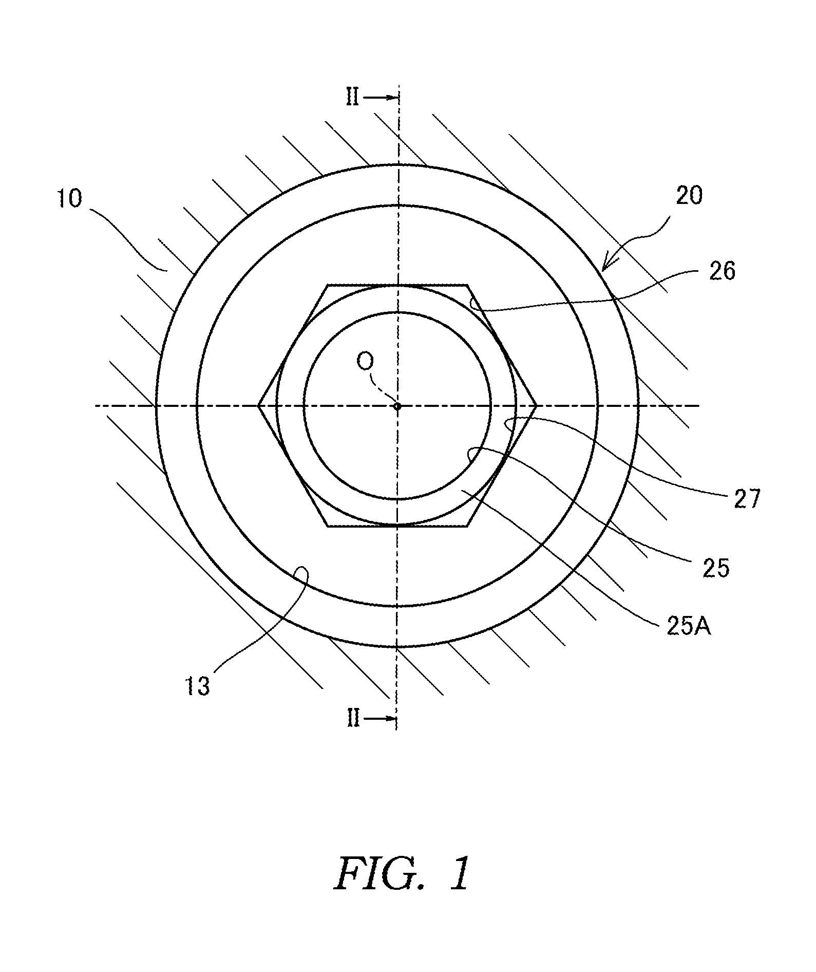
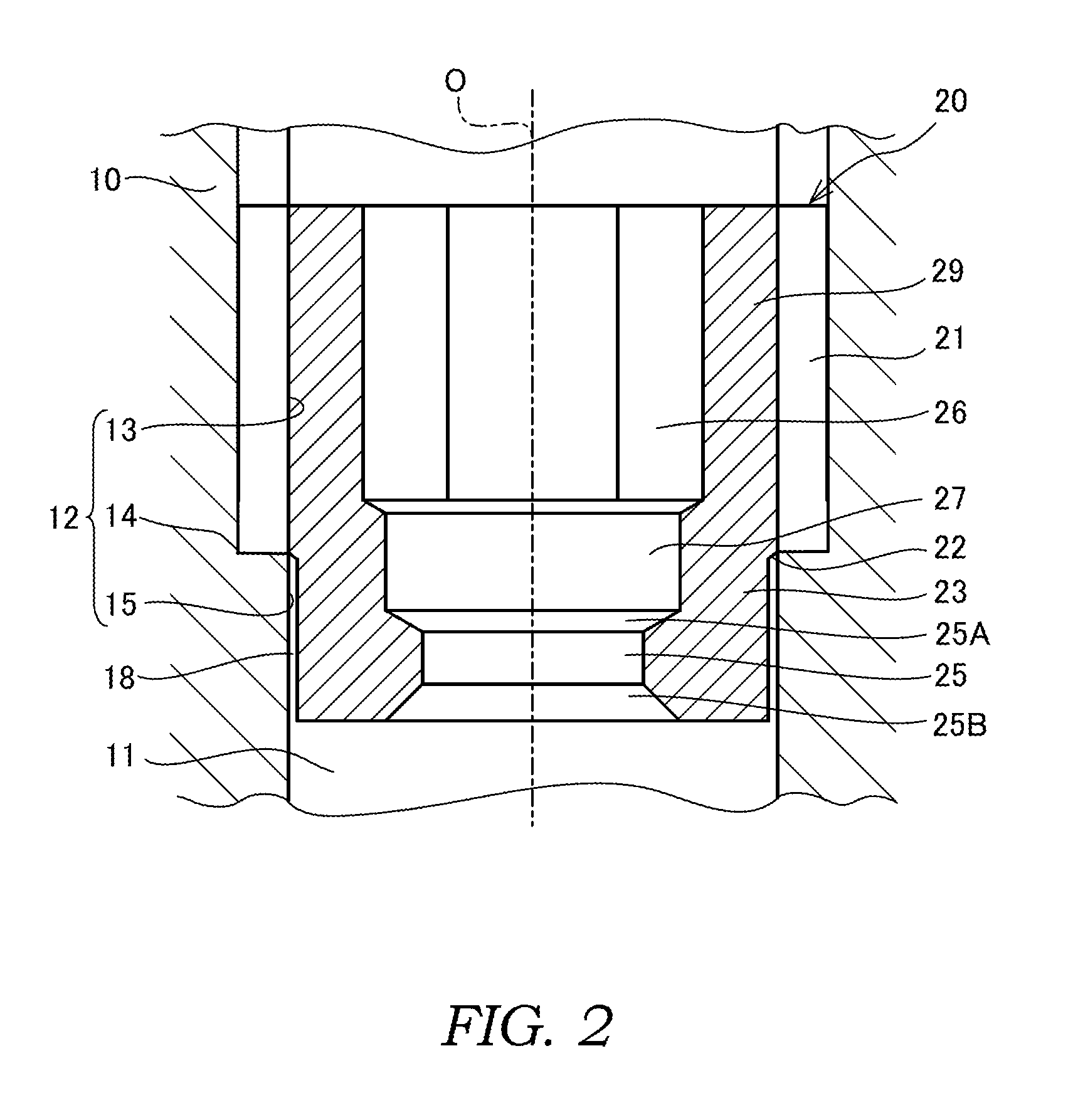
[0012]Firstly, with reference to FIGS. 1 and 2, a fluid throttle member 20 according to a first embodiment will be described.

[0013]FIGS. 1 and 2 show the fluid throttle member 20 placed in a housing 10 serving as a fluid passage member of a hydraulic pump which serves as a fluid pressure pump. The fluid throttle member 20 is to give resistance to a flow of working oil in the hydraulic pump. The fluid throttle member 20 which is applicable to the specification of the product is selected at the time of manufacturing the hydraulic pump, and assembled into the housing 10.

[0014]In the housing 10 of the hydraulic pump, a flow passage hole 11 forming an oil passage through which the working oil flows is formed. The flow passage hole 11 is a through hole having a circular flow passage section about the axis O.

[0015]An inner wall 12 of the flow passage hole 11 has a threaded portion 13 extending from one end of the flow passage hole 11, a cylindrical surface shape small diameter inner wall p...

second embodiment

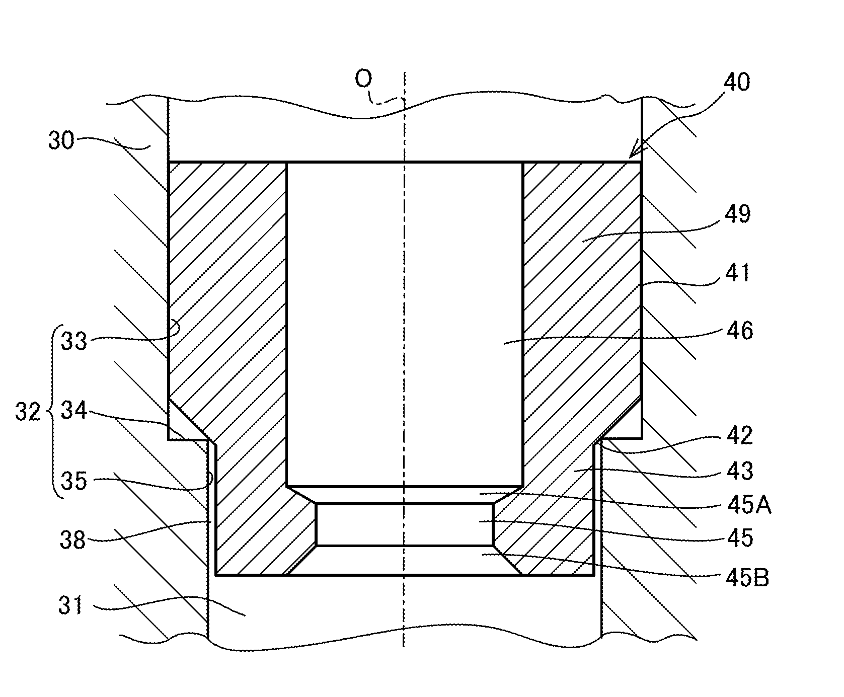
[0036]Next, with reference to FIGS. 3 and 4, a fluid throttle member 40 according to a second embodiment of the present invention will be described. In the fluid throttle member 20 according to the first embodiment, the fixing portion 29 is screwed into the threaded portion 13 of the flow passage hole 11. The second embodiment is different from the first embodiment in that a fixing portion 49 is press-fitted into an inner wall 32 of a flow passage hole 31.

[0037]In a housing 30 serving as a flow passage member of a hydraulic pump, the flow passage hole 31 forming an oil passage through which working oil flows is formed. The flow passage hole 31 is a through hole having a circular flow passage section about the axis O.

[0038]The inner wall 32 of the flow passage hole 31 has a cylindrical surface shape large diameter inner wall portion 33 having a predetermined open diameter, a cylindrical surface shape small diameter inner wall portion 35 having an open diameter smaller than the large ...


PUM


Abstract

A fluid throttle member inserted into a flow passage hole of a flow passage member, the fluid throttle member being adapted to restrict a flow of a fluid, includes a fixing portion fixed to an inner wall of the flow passage hole to form a flow passage through which the fluid flows, wherein a throttle hole is formed to be offset from the fixing portion in the axial direction of the flow passage hole, the throttle hole being adapted to restrict the flow of the fluid.

Description

TECHNICAL FIELD[0001]The present invention relates to a fluid throttle member adapted to restrict a flow of a fluid.BACKGROUND ART[0002]As a fluid throttle member adapted to restrict a flow of a fluid, JP2004-340241A discloses an orifice pin placed in a radial air bearing serving as a flow passage member that supports a rotation shaft by the air supplied into a gap between the rotation shaft and a support surface, the orifice pin being adapted to restrict a flow of the air.[0003]This orifice pin is a tubular member inserted into an orifice pin insertion hole of the radial air bearing. Inside the orifice pin, an injection hole serving as a throttle hole adapted to restrict the flow of the air supplied into the gap between the rotation shaft and the support surface is formed. The orifice pin is fixed by press-fitting an outer periphery thereof into the orifice pin insertion hole.SUMMARY OF INVENTION[0004]However, in such an orifice pin, the injection hole is deformed by stress generat...

Claims


Application Information

Patent Timeline
IPC IPC(8): F15D1/02
CPCF15D1/025F16L55/027F16L55/02754
Inventor ABE, MASAYA
Owner KYB CORP
Features
  • Generate Ideas
  • Intellectual Property
  • Life Sciences
  • Materials
  • Tech Scout
  • Unparalleled Data Quality
  • Higher Quality Content
  • 60% Fewer Hallucinations
Learn More