Electronic component assembly structure and electronic component

a technology of electronic components and assembly structures, applied in the direction of relays, coupling device connections, contacts, etc., can solve the problems of improper assembly of relays into housing members with improper arrangement, etc., to prevent improper assembly of electronic components

Active Publication Date: 2016-01-21
YAZAKI CORP
View PDF7 Cites 11 Cited by
  • Summary
  • Abstract
  • Description
  • Claims
  • Application Information

AI Technical Summary

Benefits of technology

[0011]An object of the present invention is to prevent improper assembly of an electronic component.
[0013]In this way, in order to guarantee a favorable connection to the contact portions of the lead terminals, the terminal fittings held in the housing member accommodating an electronic component, are generally disposed at positions with which the contact portions can come into contact (for example, to which the contact portions can be fitted) and are formed to correspond to the sizes of the contact portions. Accordingly, when a pair of opposite side surfaces of the component main body is reversed and the number of lead terminals or the positions or width dimensions thereof are different, the lead terminal cannot be inserted into the terminal fittings in assembling the relay with an improper arrangement and it is thus possible to satisfactorily prevent improper assembly.

Problems solved by technology

Accordingly, when the lead terminals cannot be distinguished from each other, there is a possibility that the relay will be assembled into the housing member with an improper arrangement.
Accordingly, in such a type of relay, there is a possibility that improper assembly in which the relay is assembled into the housing member with an improper arrangement will occur.

Method used


Image

  • Electronic component assembly structure and electronic component
  • Electronic component assembly structure and electronic component
  • Electronic component assembly structure and electronic component

Examples


Embodiment Construction

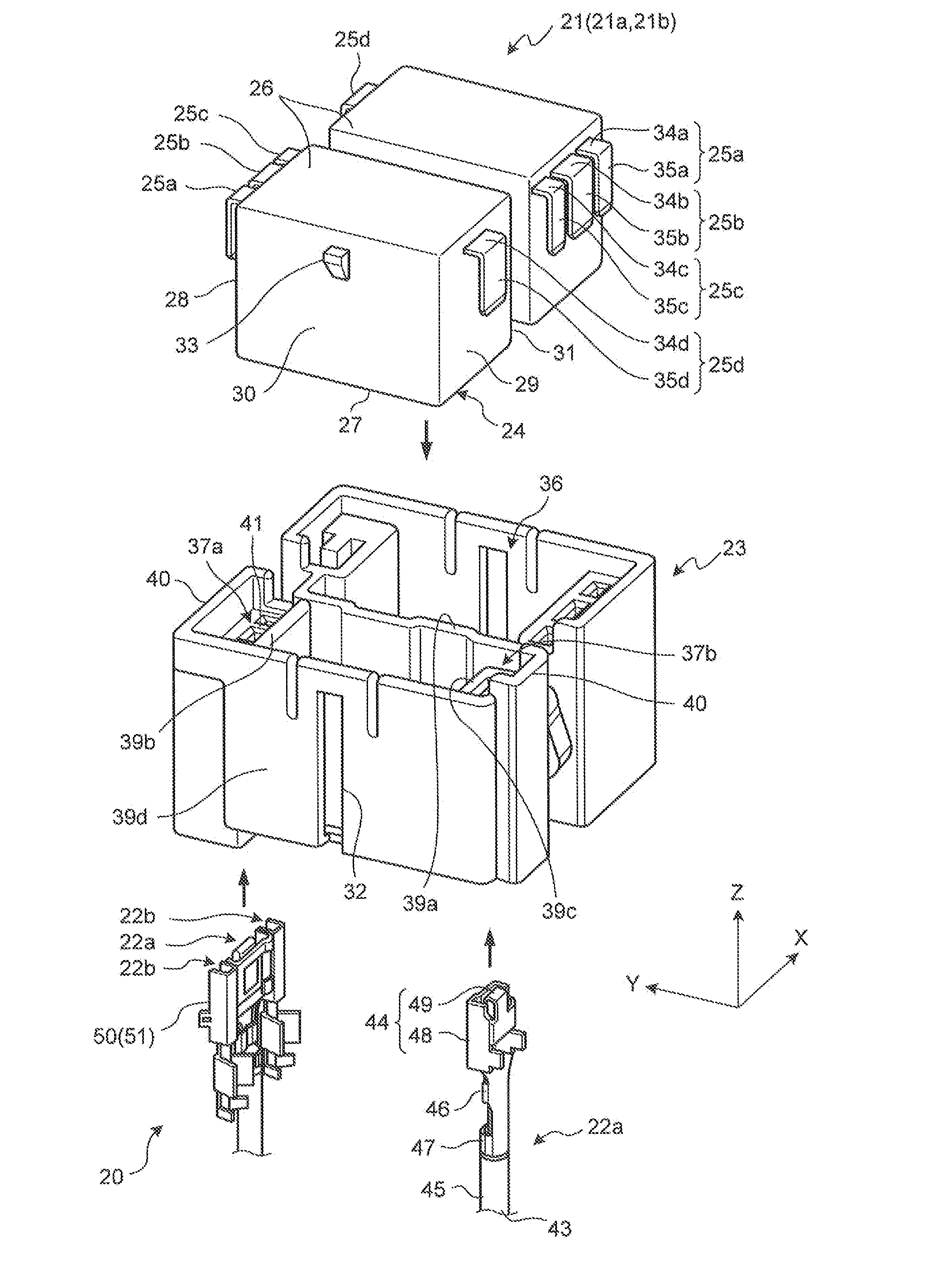
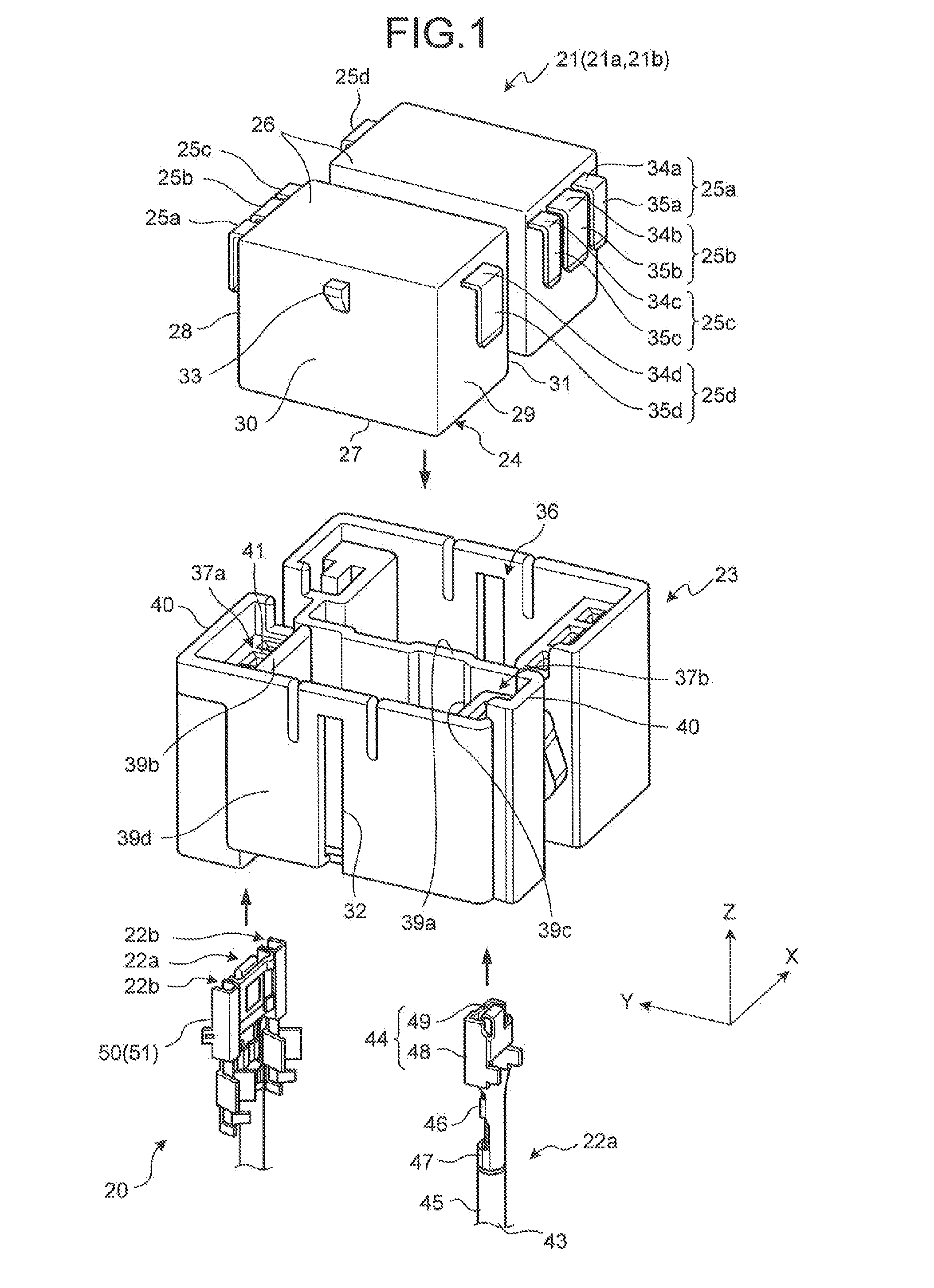
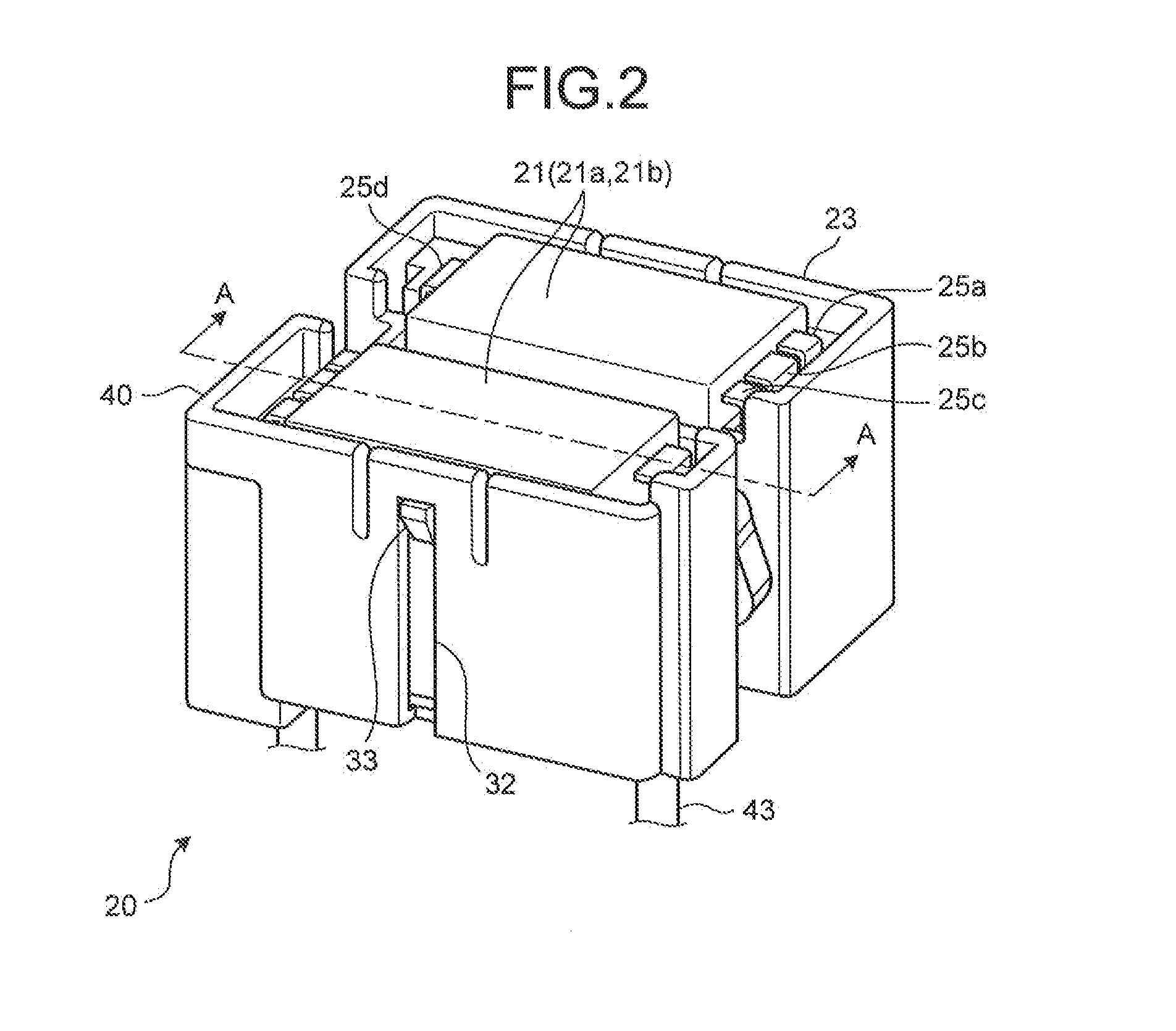
[0027]Hereinafter, an electronic component assembly structure according to the present invention will be described with reference to the accompanying drawings. In this embodiment, a relay module in which a relay is used as an electronic component and the relay is accommodated in a housing member will be described, but the electronic component assembly structure according to the present invention can be applied to electronic components other than the relay.

[0028]The use of the relay module according to this embodiment is not particularly limited, but a case can be considered in which the relay module is used for equipment or the like for controlling a connection state between a power supply device and an electric component in a moving object such as an automobile. Specifically, for example, it can be considered that the relay module is introduced into an electrical junction box (junction box) disposed between an electric component and a battery which are mounted on an automobile and ...


PUM


Abstract

An electronic component including a component main body and a plurality of lead terminals is inserted and accommodated in a housing member, the lead terminals are brought into contact with a plurality of terminal fittings held in the housing member. The lead terminals are formed such that at least one of the number of lead terminals on each side surface before and after the reversing, a distance between the contact portion and the side surface of the component main body facing the contact portion, and a width dimension in a direction perpendicular to the extending direction of the contact portion differs, when the component main body is rotated at 180 degrees to reverse the positions of the pair of opposite side surfaces of the component main body. Accordingly, it is possible to prevent improper assembly of an electronic component.

Description

CROSS-REFERENCE TO RELATED APPLICATION[0001]This application is a continuation application of International Application PCT / JP2014 / 059813, filed on Apr. 3, 2014, and designating the U.S., the entire contents of which are incorporated herein by reference.BACKGROUND OF THE INVENTION[0002]1. Field of the Invention[0003]The present invention relates to an electronic component assembly structure and an electronic component, and more particularly, to an electronic component assembly structure provided to an electrical junction box which is mounted on a moving object such as an automobile.[0004]2. Description of the Related Art[0005]In general, a moving object such as an automobile is equipped with an electrical junction box in which an electronic component such as a relay is accommodated to control connection between a power supply device and an electric component (see Japanese Patent Application Laid-open No. 2010-221787).[0006]FIG. 9 is a longitudinal-sectional view of a relay module ac...

Claims


Application Information

Patent Timeline
Patent Type & Authority Applications(United States)
IPC IPC(8): H01H45/02H01H45/14
CPCH01H45/02H01H45/14H01R13/4223H01R13/518H01R13/642H01H50/047H01H50/14H01H2050/049
Inventor KAWAMURA, YUKIHIRO
Owner YAZAKI CORP
Why Eureka
Try Eureka