Cabinet having an environment monitoring function

a technology of environment monitoring and cabinetry, applied in the field of cabinetry, can solve the problems of inability to solve problems immediately after, inability to eliminate human error in monitoring methods, and high labor costs, and achieve the effect of improving sensing accuracy

Inactive Publication Date: 2016-01-21
CYBER POWER SYST
View PDF8 Cites 24 Cited by
  • Summary
  • Abstract
  • Description
  • Claims
  • Application Information

AI Technical Summary

Benefits of technology

[0008]Further, extension lead wires can be used and respectively electrically extended from the connection interfaces for electrically connecting different sensors to the connection interfaces, enabling the sensors to be disposed at locations relatively closer to respective electronic machines in the accommodation chamber inside the cabinet body and at respective optimal angles to enhance the sensing accuracy in monitoring the temperature, humidity, smoke, airflow, air pressure, contact closure and / or access control in and around the cabinet body.

Problems solved by technology

However, according to conventional methods, this monitoring work must keep running round the clock under the control of a person, consuming much labor.
This monitoring method cannot eliminate human error.
When an unexpected condition occurs and is not found due to human error, the problem cannot be solved immediately after its occurrence.
However, prior to mounting sensors inside an electronic machine cabinet, a wiring work is necessary.
When a large number of sensors are to be installed in an electronic machine cabinet, the wiring work will be complicated and very time consuming and labor intensive.
Further, it is not easy to control sensor locations, to manage installed sensors, or keep installed sensors in accurate alignment with respective electronic machines in the electronic machine cabinet for monitoring temperature, humidity, smoke, airflow, air pressure, contact closure and other conditions accurately.

Method used


Image

  • Cabinet having an environment monitoring function
  • Cabinet having an environment monitoring function
  • Cabinet having an environment monitoring function

Examples


Embodiment Construction

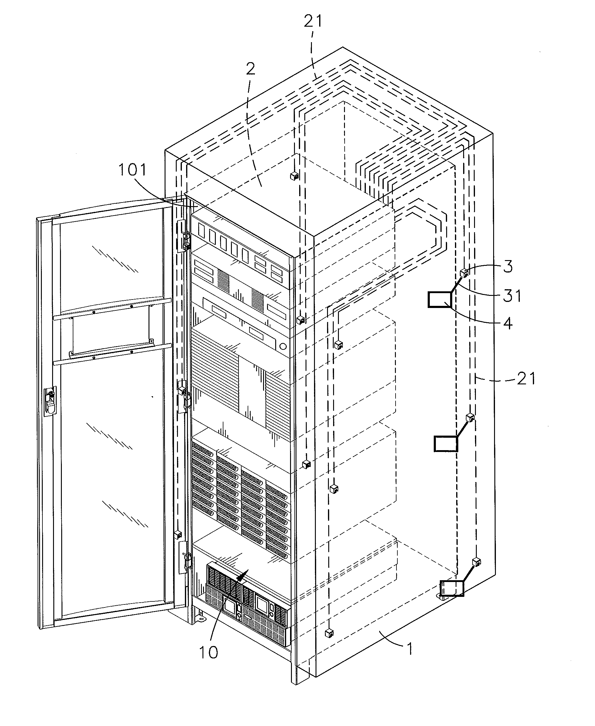
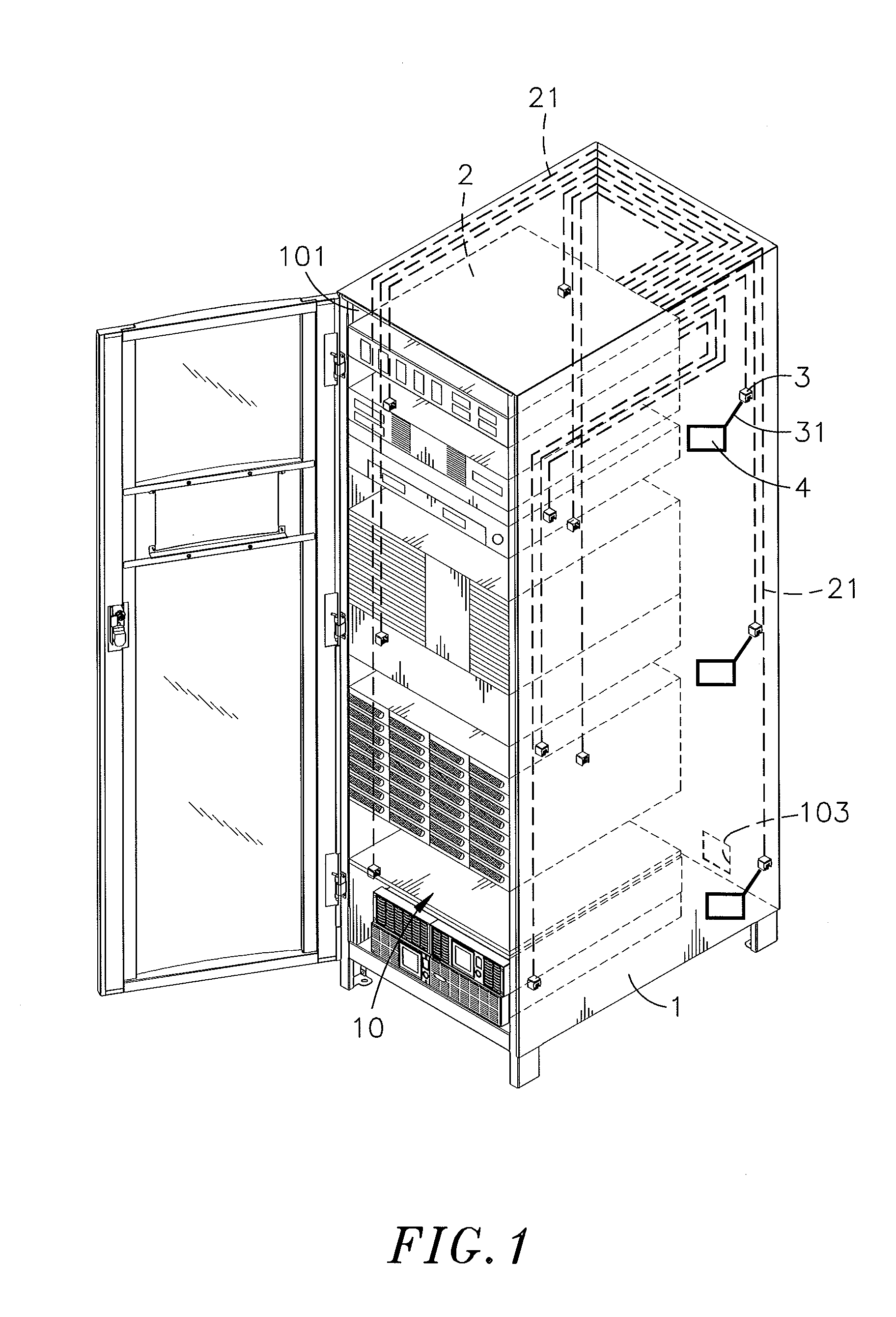
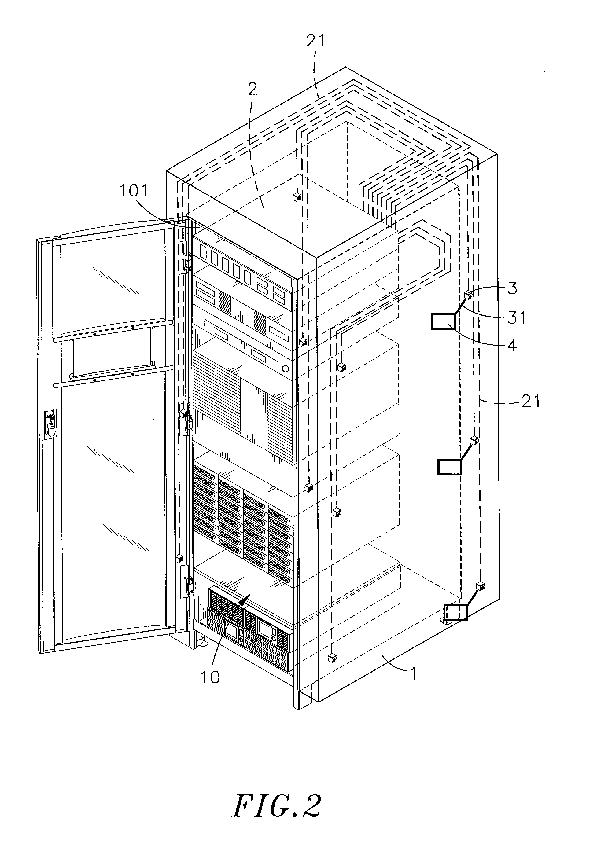
[0013]Referring to FIGS. 1-4, a cabinet having an environment monitoring function in accordance with the present invention is shown. The cabinet comprises a cabinet body 1, a monitoring system main unit 2, and a plurality of connection interfaces 3.

[0014]The cabinet body 1 defines therein an accommodation chamber 10 adapted for accommodating various electronic machines such as servers, modems, switching systems, routers and / or other IT (information technology) equipment and machines.

[0015]The monitoring system main unit 2 has electrically connected thereto a plurality of signal lines 21. The connection interfaces 3 are respectively connected to the signal lines 21 remote from the monitoring system main unit 2. Further, the connection interfaces 3 can be plug type or socket type electric connectors.

[0016]During installation of the present invention, mount the monitoring system main unit 2 in the accommodation chamber 10 inside the cabinet body 1 to let the signal lines 21 be arranged...


PUM


Abstract

A cabinet includes a cabinet body defining therein an accommodation chamber for accommodating electronic machines such as servers, modems, switching systems, routers and / or other IT (information technology) equipment and machines, a monitoring system main unit mounted in the accommodation chamber of the cabinet body and having signal lines thereof arranged along horizontal top surface and vertical lateral surfaces of an inside wall of the cabinet body, a plurality of connection interfaces respectively connected to the signal lines remote from the monitoring system main unit, and different sensors respectively connected to the connection interfaces to face toward the servers, modems, switching systems, routers and / or other IT (information technology) equipment and machines in the accommodation chamber for monitoring temperature, humidity, smoke, airflow, air pressure, contact closure and / or access control.

Description

BACKGROUND OF THE INVENTION[0001]1. Field of the Invention[0002]The present invention relates to cabinets and more particularly, to a cabinet having an environment monitoring function that has a monitoring system main unit mounted in the cabinet body thereof and a plurality of connection interfaces respectively electrically connected to respective signal lines of the monitoring system main unit and fixedly disposed at different locations inside the cabinet body for the installation of different sensors for monitoring temperature, humidity, smoke, airflow, air pressure, contact closure and / or access control.[0003]2. Description of the Related Art[0004]With the continuous improvement of socio-economic, national income has been continuously increased. In consequence, small and medium-sized enterprises as well as large-sized companies are more likely to be active. Further, company staffs need to use telecommunication equipment for operating electronic machines such as telephones, networ...

Claims


Application Information

Patent Timeline
Patent Type & Authority Applications(United States)
IPC IPC(8): H05K5/02
CPCH05K5/0247H05K7/1498H05K7/20736H05K7/20836
Inventor CHIEN, HUNG-CHUN
Owner CYBER POWER SYST
Why Eureka
Try Eureka