Imaging element, imaging device, endoscope, endoscope system, and method of driving imaging element

a technology of imaging elements and imaging devices, applied in the field of imaging elements, can solve problems such as difficult to dissipate heat and distortion of images

Active Publication Date: 2016-01-28
OLYMPUS CORP
View PDF6 Cites 14 Cited by
  • Summary
  • Abstract
  • Description
  • Claims
  • Application Information

AI Technical Summary

Problems solved by technology

Thus in the initial part of the imaging signal period, fluctuation in power consumption causes the power source voltage to fluctuate, which results in distortion

Method used


Image

  • Imaging element, imaging device, endoscope, endoscope system, and method of driving imaging element
  • Imaging element, imaging device, endoscope, endoscope system, and method of driving imaging element
  • Imaging element, imaging device, endoscope, endoscope system, and method of driving imaging element

Examples


embodiment

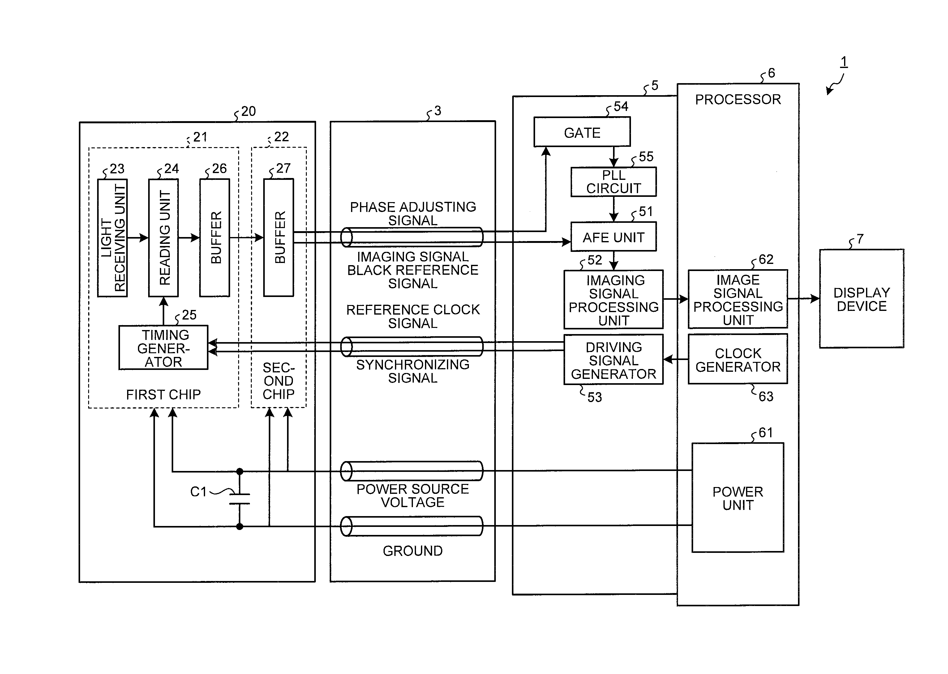
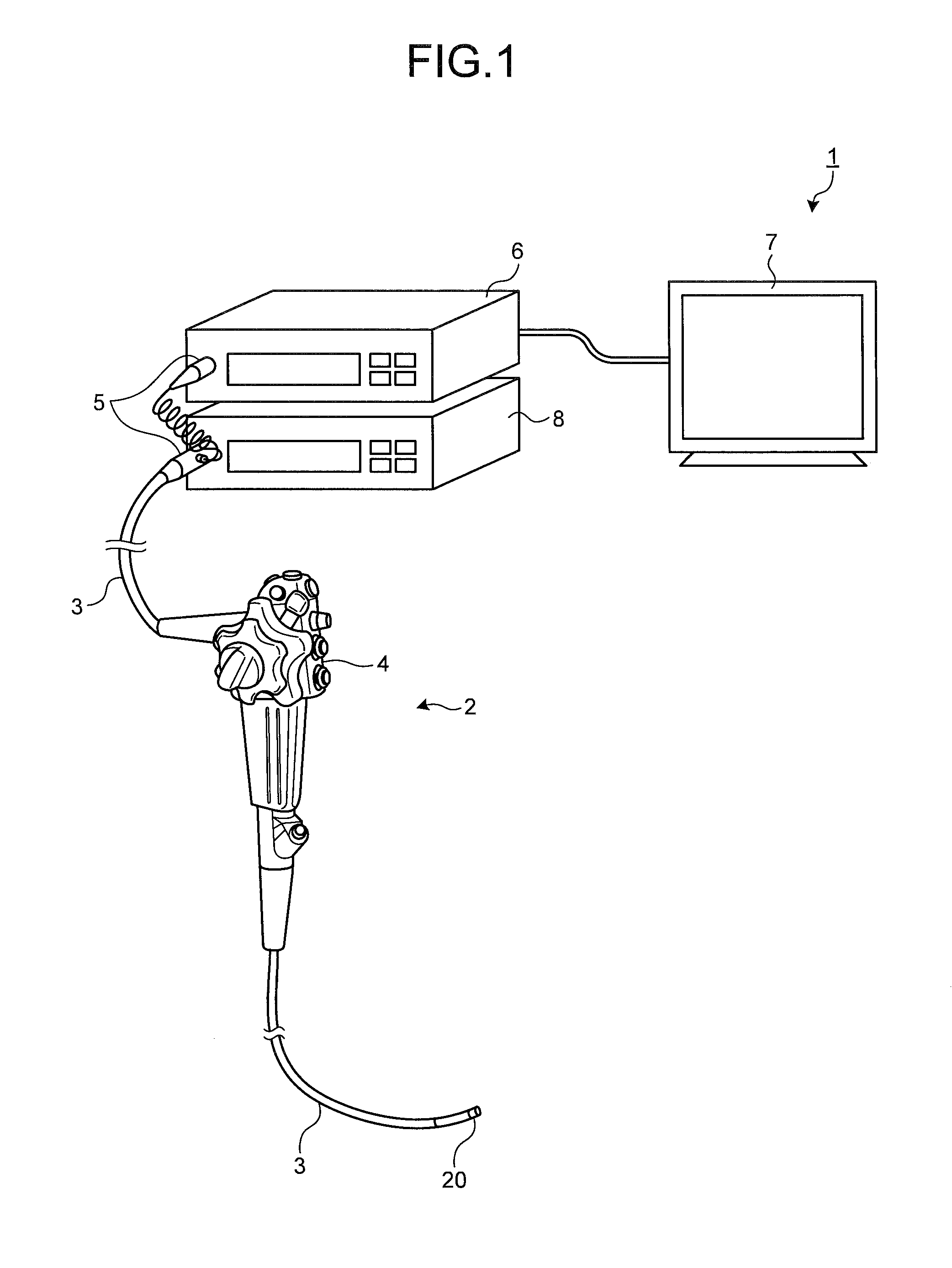
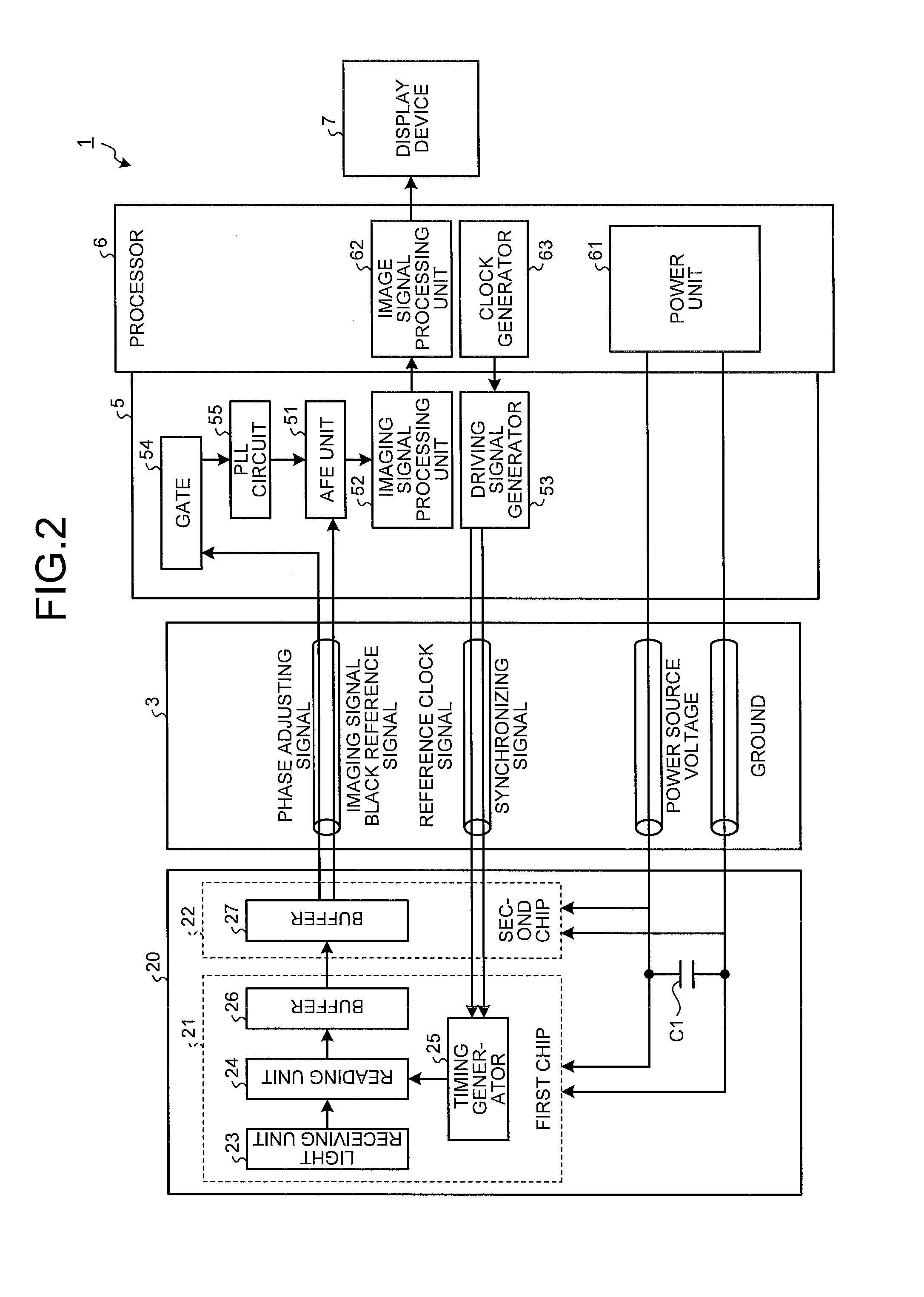
[0021]FIG. 1 schematically illustrates an overall configuration of an endoscope system according to a first embodiment of the present invention. An endoscope system 1 illustrated in FIG. 1 includes an endoscope 2, a transmission cable 3, a connecting unit 5, a processor (control device) 6, a display device 7, and a light source device 8. The endoscope 2 is configured to take an in-vivo image in a subject with an insertion part which is a portion of the transmission cable 3 inserted in a body cavity of the subject and output imaging signals. The transmission cable 3 couples together the endoscope 2 and the connecting unit 5. The connecting unit 5 is coupled to the endoscope 2, the processor 6, and the light source device 8. The connecting unit 5 performs predetermined signal processing to imaging signals output from the coupled endoscope 2 and analogue-digital conversion (A / D conversion) to convert the imaging signals into image signals, and outputs image signals. The processor 6 per...


PUM


Abstract

An imaging element includes: a plurality of pixels; first vertical transfer lines; a second vertical transfer line; a reference voltage generator configured to generate a first reference voltage for a column-black reference signal, a second reference voltage for a line-black reference signal and a third reference voltage for phase adjustment; a phase adjusting signal generator configured to output a phase adjusting signal corresponding to the third reference voltage; a first reference signal generator configured to generate a column-black reference signal corresponding to the first reference voltage; a second reference signal generator configured to generate a line-black reference signal corresponding to the second reference voltage; and a timing generator configured to drive the phase adjusting signal generator, the first reference signal generator and the second reference signal generator to transmit the phase adjusting signal, the column-black reference signal and the line-black reference signal, respectively.

Description

CROSS-REFERENCE TO RELATED APPLICATIONS[0001]This application is a continuation of PCT international application Ser. No. PCT / JP2014 / 059455 filed on Mar. 31, 2014 which designates the United States, incorporated herein by reference, and which claims the benefit of priority from Japanese Patent Applications No. 2013-092394, filed on Apr. 25, 2013, incorporated herein by reference.BACKGROUND OF THE INVENTION[0002]1. Field of the Invention[0003]The present invention relates to an imaging element, an imaging device, an endoscope, an endoscope system, and a method of driving an imaging element.[0004]2. Description of the Related Art[0005]In an imaging device including a complementary metal-oxide semiconductor (CMOS) imaging element, power consumption differs between a blanking period and an imaging signal period. Thus in the initial part of the imaging signal period, fluctuation in power consumption causes the power source voltage to fluctuate, which results in distortion of an image.[00...

Claims


Application Information

Patent Timeline
IPC IPC(8): A61B1/00A61B1/045H04N5/225H04N7/18
CPCA61B1/00006H04N7/183H04N2005/2255A61B1/045A61B1/00009H04N5/2253G02B23/2476A61B1/05H04N23/555H04N25/63H04N25/65H04N25/709H04N25/75A61B1/000095H04N23/54H04N25/71
Inventor AKAHANE, NANAONO, MAKOTONISHIWAKI, TAKAHIROHOSOGAI, KATSUMI
Owner OLYMPUS CORP
Why Eureka
Try Eureka