Clamp with ratchet device

a ratchet device and clamping technology, applied in the field of clamps, can solve the problems of insufficient clamping force, inconvenient use of the lever, and failure to meet the requirement of tightly and stably clamping the target object, and achieve the effect of enhancing the clamping effect and facilitating the force exertion

Active Publication Date: 2016-01-28
EHOMA INDAL CORP
View PDF0 Cites 4 Cited by
  • Summary
  • Abstract
  • Description
  • Claims
  • Application Information

AI Technical Summary

Benefits of technology

[0013]Further, the ratchet device of the present invention is provided with a main body. The main body has a head part and a grip part extending from the head part. The first end of the thread rod has a ratchet part, while the main body is pivotally provided with a ratchet block for engaging the ratchet part. Also, the ratchet block is allowed to swing between a first position and a second position, facilitating the ratchet device being operated between the idling position and the driving position.
[0015]Therefore, user operates the ratchet device for driving the thread rod to reciprocate, facilitating the usage of the present invention in a narrow space. Also, during the driving process, force is efficiently exerted on the thread rod for enhancing the clamping effect, providing an acceleration of operation and an easiness of force exertion.

Problems solved by technology

However, when the pressure plate pushes and presses the target object, the user is unable to make the pressure plate further exert additional pressure upon the target object through the lever element, failing to meet the requirement of tightly and stably clamping the target object.
However, in a narrow operational environment, exerting the clamping force by use of the lever is inconvenient, and the clamping force exerted might be insufficient.
Also, an exposed spring is disposed between the handle and the main body; as a result, other objects may be accidentally hooked, causing the handle to be malfunctioned.

Method used


Image

  • Clamp with ratchet device
  • Clamp with ratchet device
  • Clamp with ratchet device

Examples


Embodiment Construction

[0025]The aforementioned and further advantages and features of the present invention will be understood by reference to the description of the preferred embodiment in conjunction with the accompanying drawings where the components are illustrated based on a proportion for explanation but not subject to the actual component proportion.

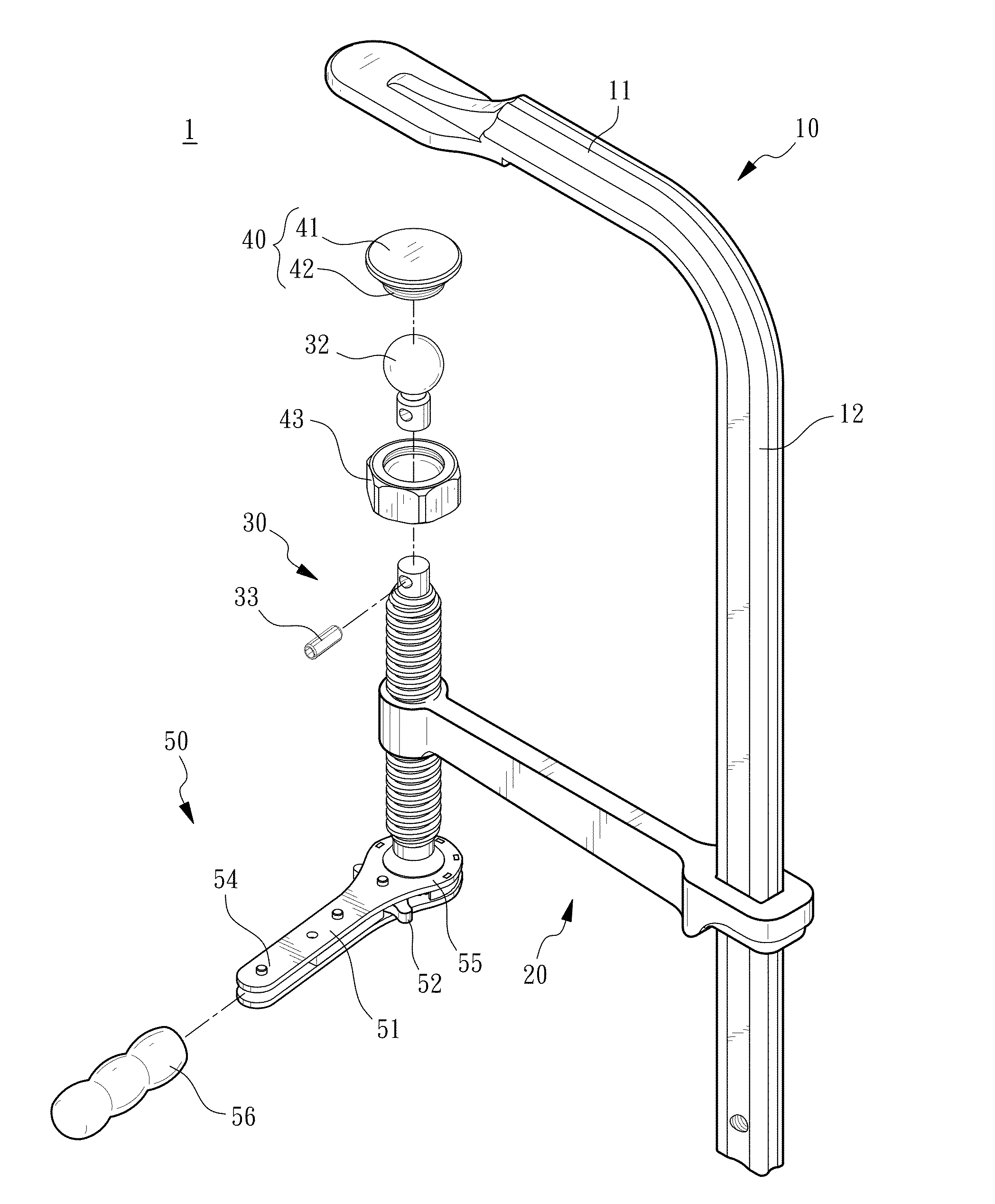
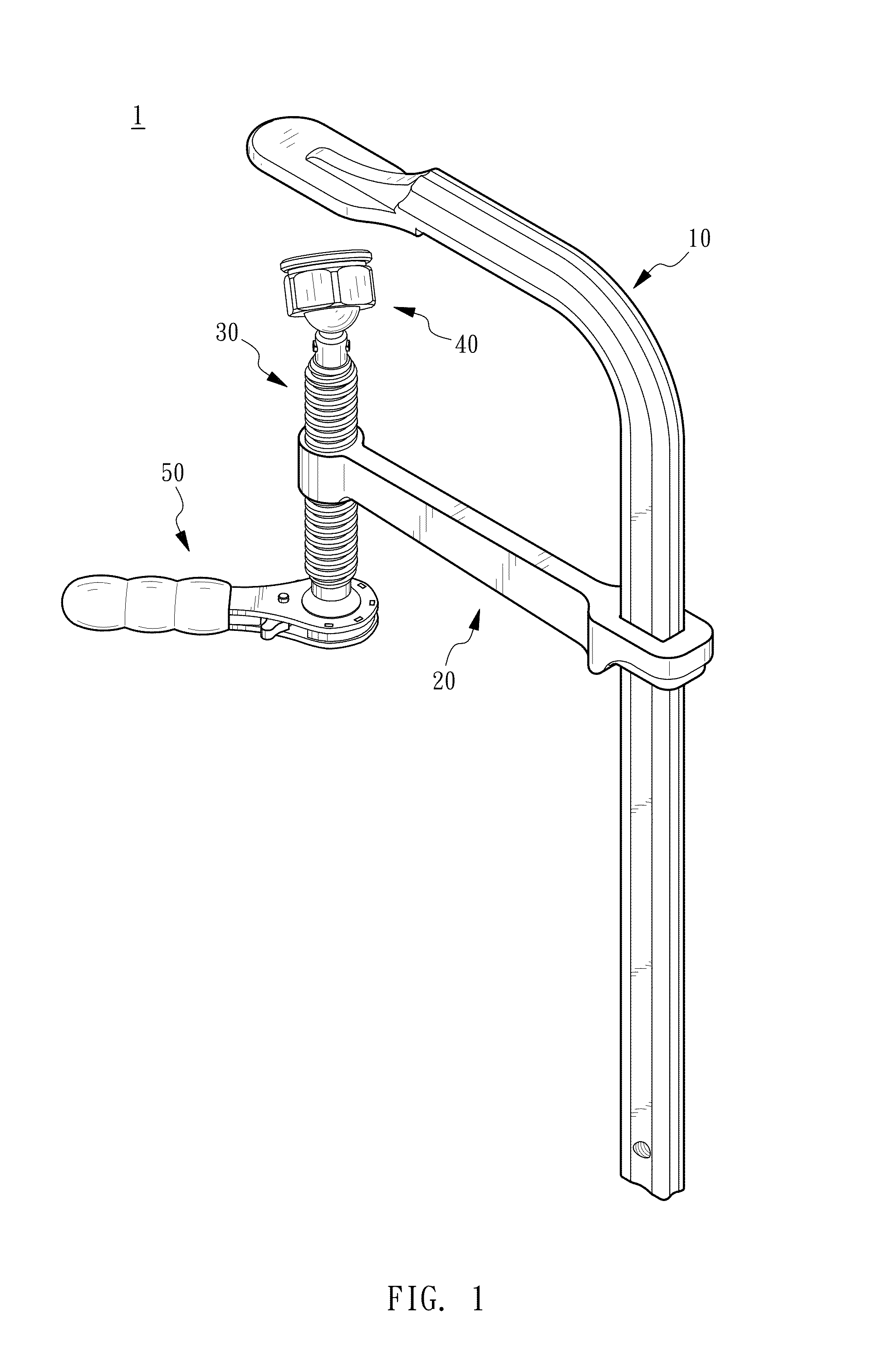
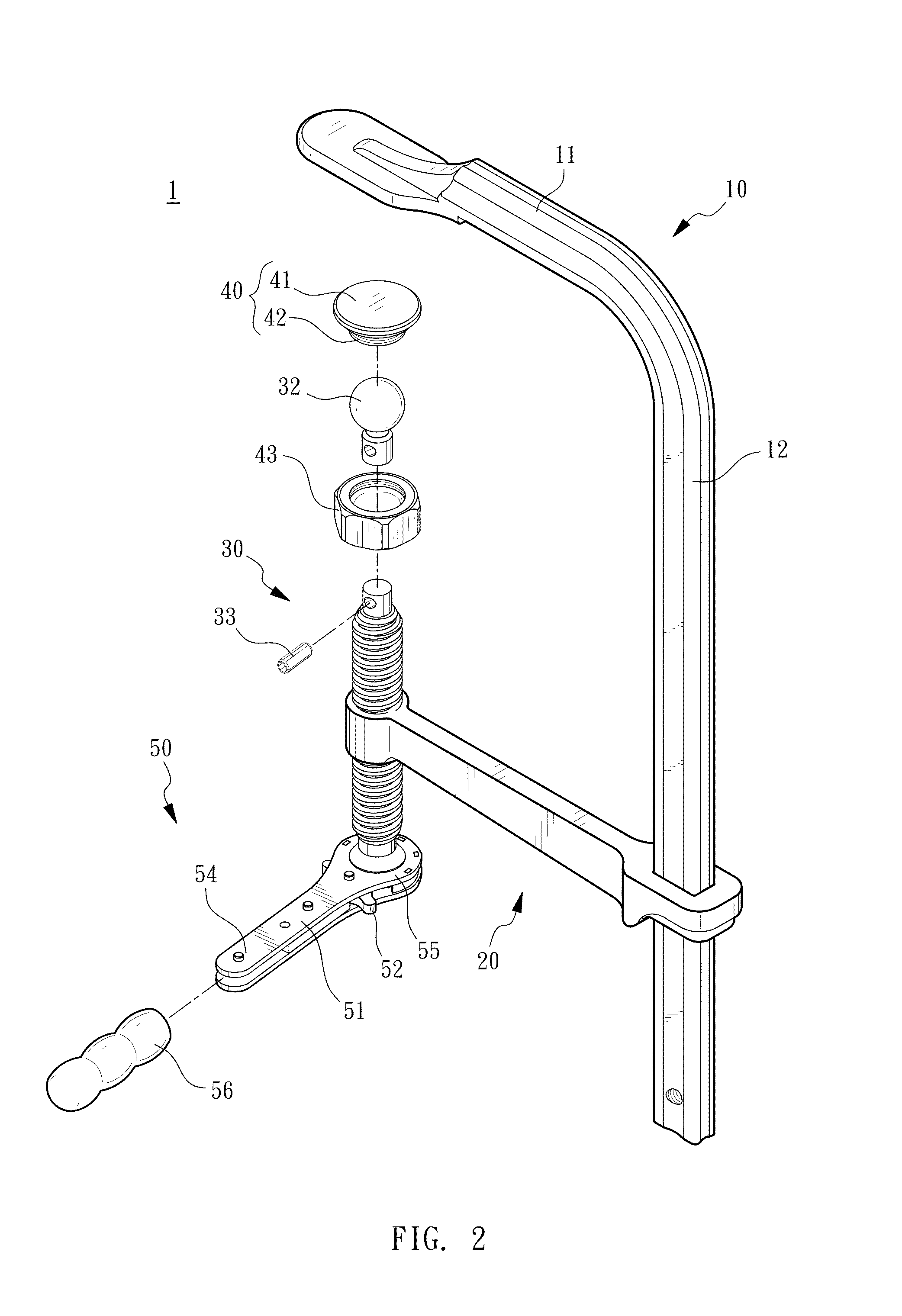
[0026]Referring to FIG. 1 to FIG. 4, a clamp 1 with ratchet device of the present invention, as shown by the embodiment present as an F-clamp, comprises a clamp body 10, an installation part 20, a thread rod 30, a clamping member 40, and a ratchet device 50. The thread rod 30 is driven to move by the ratchet device 50, whereby the clamping member 40 and the clamp body 10 clamps a target object 2.

[0027]The clamp body 10 is in an L shape, having a fixed part 11, and a slide rail 12 disposed on one end of the fixed part 11, while the fixed part 11 and the slide rail 12 are integrally formed.

[0028]One end of the installation part 20 mounts around the slide...


PUM


Abstract

A clamp with ratchet device for clamping a target object includes a clamp body, a thread rod, a clamping member, and a ratchet device. Therein, the clamp body has a fixed part and an installation part. The thread rod is movably disposed on the installation part and having a first end and a second end. The clamping member is disposed on the second end of the thread rod. The ratchet device is combined to a first end of the thread rod and operated between an idling position and a driving position. The ratchet device is able to drive the thread rod to rotate and move toward and away from the fixed part at the driving position and idle against the thread rod at the idling position. Therefore, the clamp is allowed to be operated in a narrow space.

Description

BACKGROUND OF THE INVENTION[0001]1. Field of the Invention The present invention relates to clamps, and more particularly, to a clamp with ratchet device.[0002]2. Description of the Related Art[0003]A clamp usually has a configuration including a fixed part and an active part, wherein the active part is allowed to be moved toward or away from the fixed part, thereby clamping a target object and achieving different operational demands.[0004]U.S. Pat. No. 8,025,275 discloses a single hand operated ratchet clamp, comprising a slide rail, a sliding arm, a fixed arm, a lever element, and a pressure plate. When clamping an object, user grips the slide rail with one hand and uses the lever element to move the sliding arm toward the fixed arm with the other hand. When the target object is to be clamped, through deflecting the lever element, the pressure plate rapidly pushes and presses the target object, achieving a one-hand operation. However, when the pressure plate pushes and presses the...

Claims


Application Information

Patent Timeline
Patent Type & Authority Applications(United States)
IPC IPC(8): B25B5/10B25B5/16B25B13/46
CPCB25B5/101B25B13/46B25B5/16B25B5/102
Inventor CHUANG, CHUN-HUAN
Owner EHOMA INDAL CORP
Why Eureka
Try Eureka