

Universal Joint Dismantling Tool
- Summary
- Abstract
- Description
- Claims
- Application Information
AI Technical Summary
Benefits of technology
Problems solved by technology
Method used
Image

Examples
embodiment 10
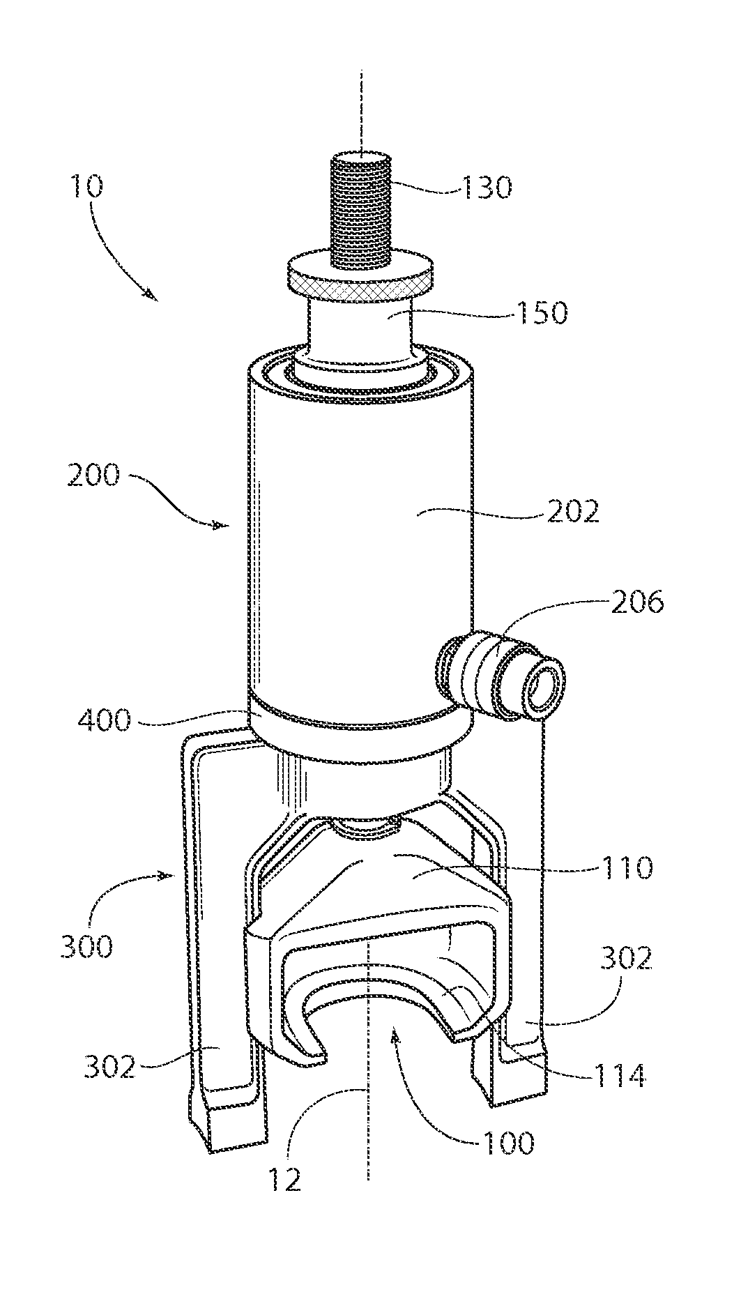
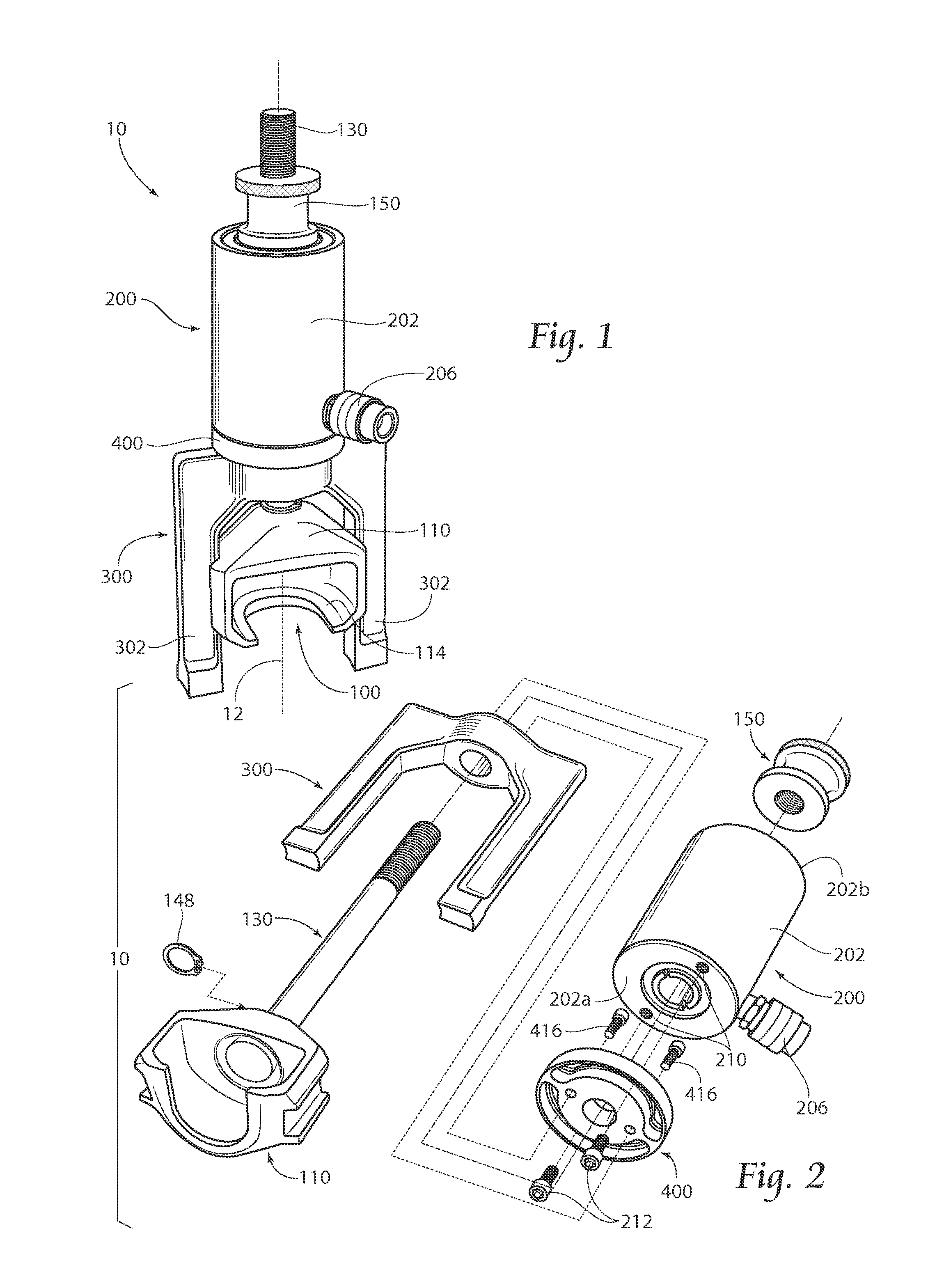
[0054]The actuator 200 is coupled to the yoke 300. In this embodiment 10, threaded fasteners 212 are inserted through the pivot channels 412,414 in the disk 400 and mated with threaded apertures 210 on the cylinder 202. While these fasteners 212 may be securely tightened, so as to fix the actuator 200 in a substantially immovable relationship with the disk 400 and, in turn, the yoke 300, it is preferred to refrain from tightening the fasteners 212. In this fashion, although the cylinder 200 is coupled to the yoke 300, the cylinder 200 is left to freely rotate about the pulling axis 12.
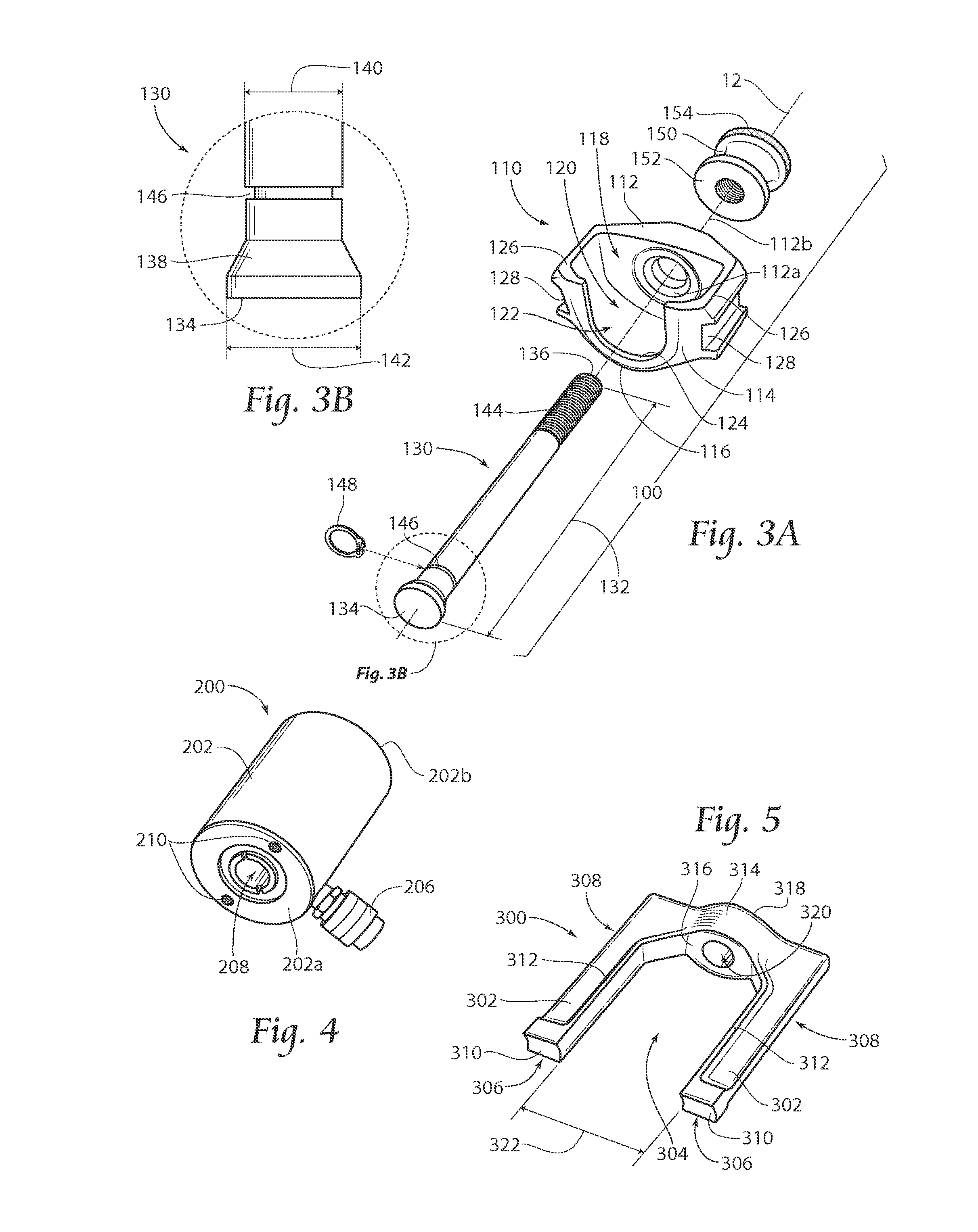
[0055]The top end 136 of the shaft 130 is inserted through the actuator 200 and the knob 150 is threaded onto the shaft 300, or otherwise positioned thereon. The cup 110 is preferably positioned within the pulling gap 304 defined by the yoke 300, and may be rotatably registered by interfacing the registration race(s) 128 with the guide rail(s) 312 provided along the legs 302. Once this basic assembly i...
second embodiment
[0065]FIG. 11 shows the tool 20 previously described, further including a bearing cap safety device 80 for containing a popped bearing cap 76. The safety device 80 generally includes a patch of flexible material 82, such as leather or canvas, coupled to the tool 20 such as by using elastic retaining members 84 hooked to the handle 22, bracket 26 or an aperture 29 specifically suited for same. The patch of material 82 is generally placed to cover the bearing cap 76 intending to be removed by the use of the tool 20. FIG. 12 shows the safety device 80 having been disconnected from the tool 20 and folded or rolled up for storage in the handle 22 thereof.
embodiment 300
[0066]An alternative yoke 300′ is shown in FIG. 13. This yoke 300′ is similar to the first yoke embodiment 300, except that the functionality of the coupling disk 400 has been incorporated. Specifically, a coupling disk 370 has been provided as integrally formed with the yoke bridge 314, including a central pedestal member 372 disposed about the yoke throughbore 320′. The disk 370 further includes an annular ring 374 spaced from the pedestal member 372 by a circumferential countersunk slot 376. The countersunk slot 376 serves the same function as the countersunk slots 412,414 previously discussed, but it 376 provides for 360 degrees of rotational positionability of the cylinder 202. Relief slots 376 may be provided on diametrically opposed sides of the pedestal member to allow access to the threaded fasteners 212 to securely couple the cylinder 202 to the yoke 300′ in any position throughout the 360 degrees of rotation allowed. FIG. 14 shows the coupling of the alternative yoke 300′...
PUM
 Abstract
Description
Claims
Application Information