
Method for installing an object using an unmanned aerial vehicle

a technology of unmanned aerial vehicles and objects, applied in the field of aerial operations, can solve the problems of a large threat to low flying aircraft and birds, wires and cables are particularly dangerous to helicopters, and 40-50% of the resulting accidents are fatal, so as to achieve safe and reliable installation of aerial markers without risking the lives of pilots and linemen or expensive equipment, and increase the scope and range of installation locations. cost effective

Active Publication Date: 2016-01-28
MCNALLY JONATHAN
View PDF10 Cites 139 Cited by
  • Summary
  • Abstract
  • Description
  • Claims
  • Application Information

AI Technical Summary

Benefits of technology

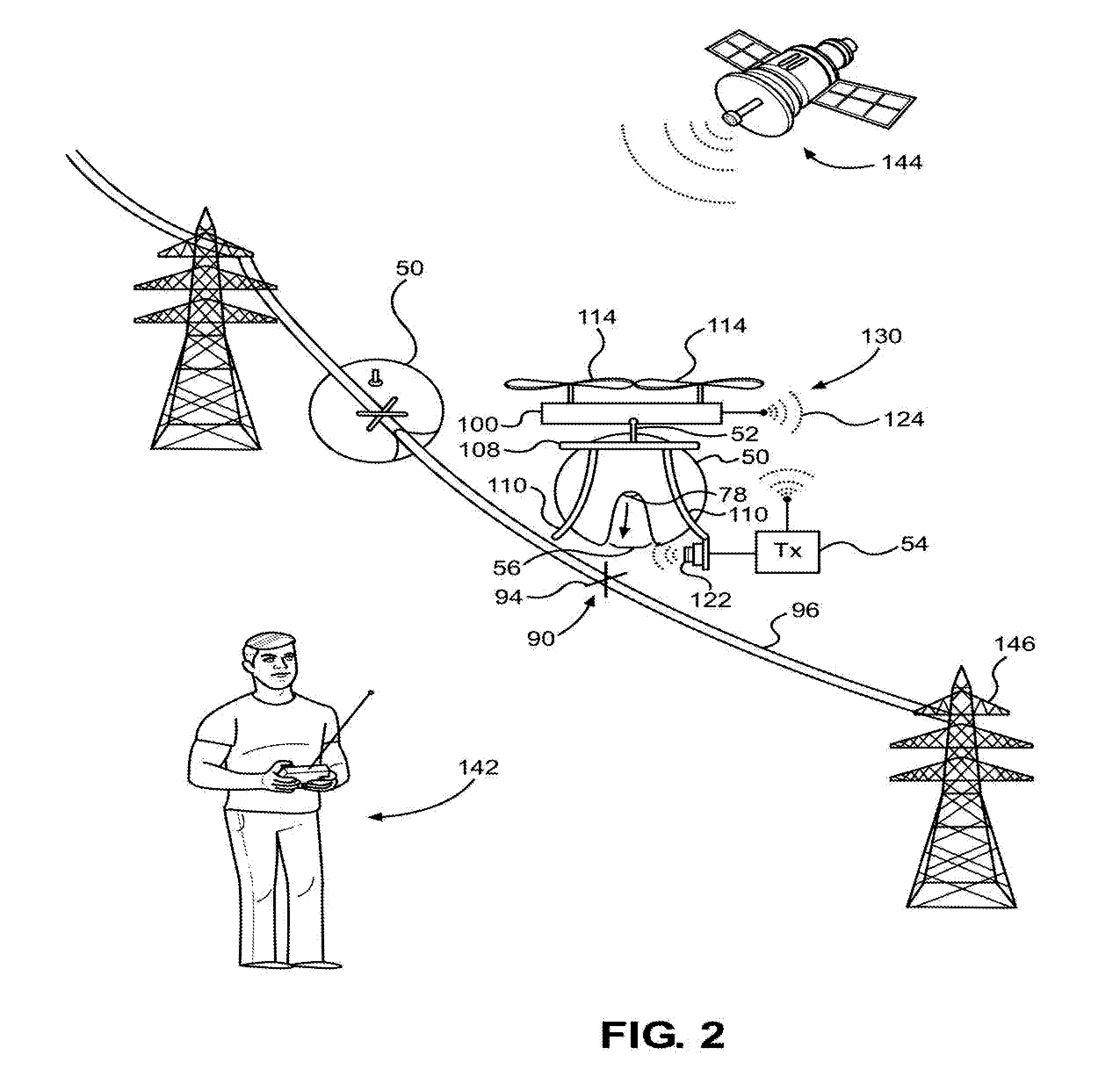
The present invention provides a safe, inexpensive, and automated apparatus and method for lifting and attaching an aerial market to a cable span under a variety of landscape and infrastructure conditions. The method involves using a UAV platform, a flight control system modified for reverse thrust and bottom-tether conditions, a releasable hoist, automatic cable fasteners, an aerial marker ball, proximity sensors, gimbal systems for stabilization, and cable contact sensors, among others. The apparatus includes a UAV platform, a flight control system, a releasable hoist, automatic cable fasteners, an aerial marker ball, proximity sensors, gimbal systems for stabilization, and cable contact sensors, among others. The invention has advantages such as reducing costs, increasing safety, and expanding installation locations. It also includes self-optimizing catenary maps to improve location accuracy.

Problems solved by technology

Wires and cables are a major threat to low flying aircraft and birds.
Due to the limitations of vision and the inconspicuous nature of wires, wires can be invisible until it is too late and a collision occurs, usually with disastrous results.
Wires are particularly dangerous to helicopters; which, owing to their unique capabilities and mission requirements, often operate at low altitudes.
Wire strikes are a leading cause of helicopter accidents worldwide with the FAA estimating that wires claim an average of 100 helicopters a year.
When a wire strike occurs, 40-50% of the resulting accidents are fatal.
However, ground based installation is often impractical or impossible due to the hazard's height, geographical remoteness, or the underlying surface (lakes, rivers, rough terrain, etc).
This method appears to be effective and safe, but cumbersome, time consuming, and impractical for many installations.
The robot must be attached and detached to the cables; which can be a challenging affair; and cannot overcome obstacles on the wire, thus limiting it to one span of cable at a time.
The cumbersome and time-consuming drawbacks of this method should be obvious and are similar to the crawling robot method, except with the additional hazard of involving a human life suspended on live high voltage transmission wires.
This method has seen limited use and is somewhat cumbersome; and, as with previously described methods, is often impractical or impossible.
Additionally, the design of the automatic fastening mechanism is somewhat complex and significantly heavier than simplified designs which is undesirable as weight is a crucial concern for objects suspended on overhead cables.
However, the helicopter installation methods are performed at great risk to the pilot and lineman involved.
The helicopter installation method requires highly trained and exceptionally skilled linemen and pilots and is one of the toughest jobs they are asked to accomplish.
In the event of an emergency such as mechanical failure or a wire strike with the helicopter blades, the lineman and pilot will most likely die.
There is also risk of significant damage to property and lost revenue due to damaged utility infrastructure.
In addition to the pilot and crew, the operating and insurance costs of the helicopter make this method extremely expensive.
The high cost of installation of aerial markers is generally covered by a utility company who then passes the costs on to their customers.
Due to the high cost of installation, many threatening objects are left unmarked leaving a substantial risk to low flying aircraft and birds.

Method used


Image

  • Method for installing an object using an unmanned aerial vehicle
  • Method for installing an object using an unmanned aerial vehicle
  • Method for installing an object using an unmanned aerial vehicle

Examples


Embodiment Construction

[0055]The following description is not to be taken in a limiting sense, but is made merely for the purpose of describing the general principles of exemplary embodiments; many additional embodiments of this invention are possible. It is understood that no limitation of the scope of the invention is thereby intended. The scope of the disclosure should be determined with reference to the Claims. Reference throughout this specification to “one embodiment,”“an embodiment,” or similar language means that a particular feature, structure, or characteristic that is described in connection with the embodiment is included in at least one embodiment of the present disclosure. Thus, appearances of the phrases “in one embodiment,”“in an embodiment,” and similar language throughout this specification may, but do not necessarily, all refer to the same embodiment.

[0056]Further, the described features, structures, or characteristics of the present disclosure may be combined in any suitable manner in ...


PUM


Abstract

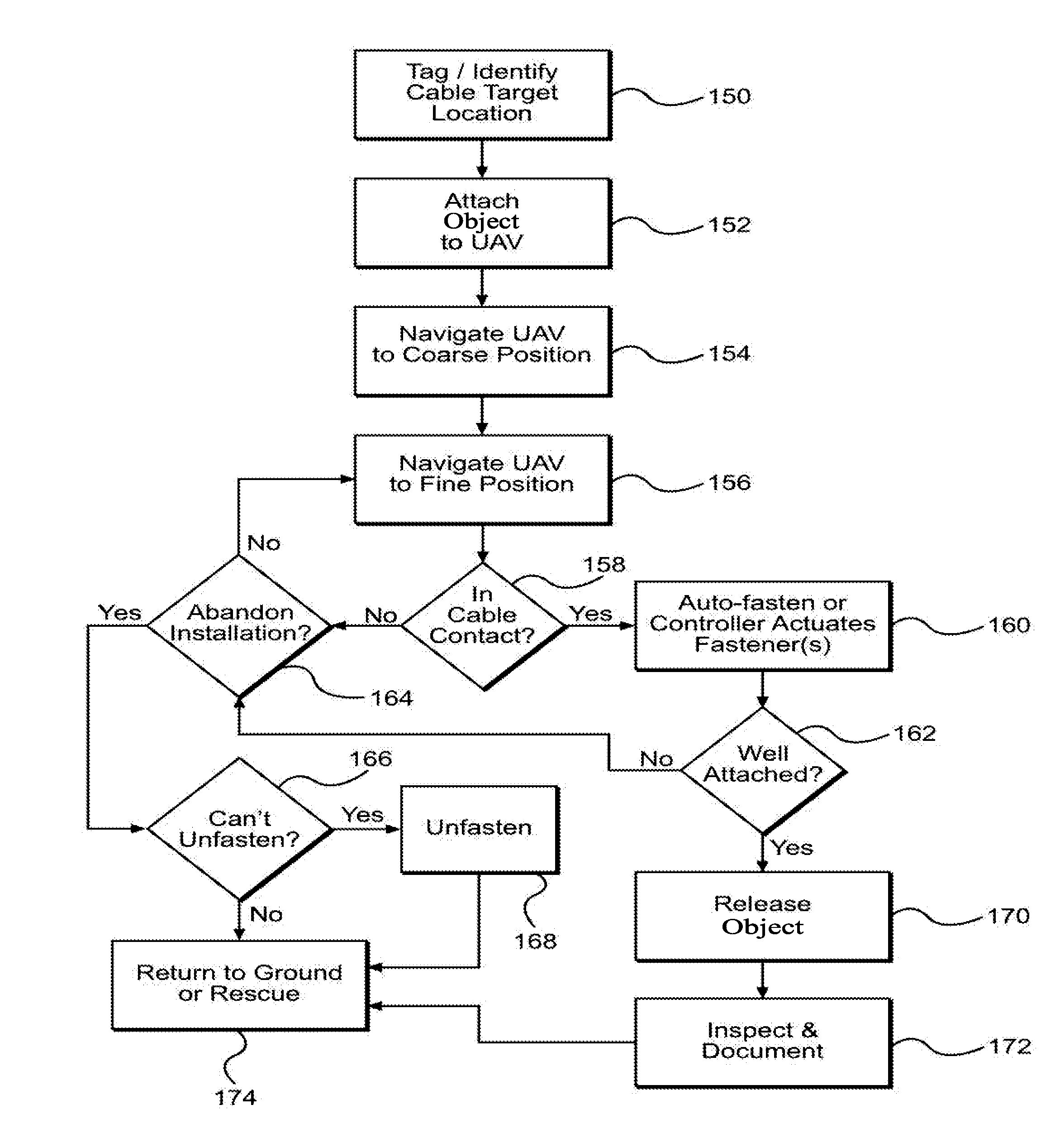
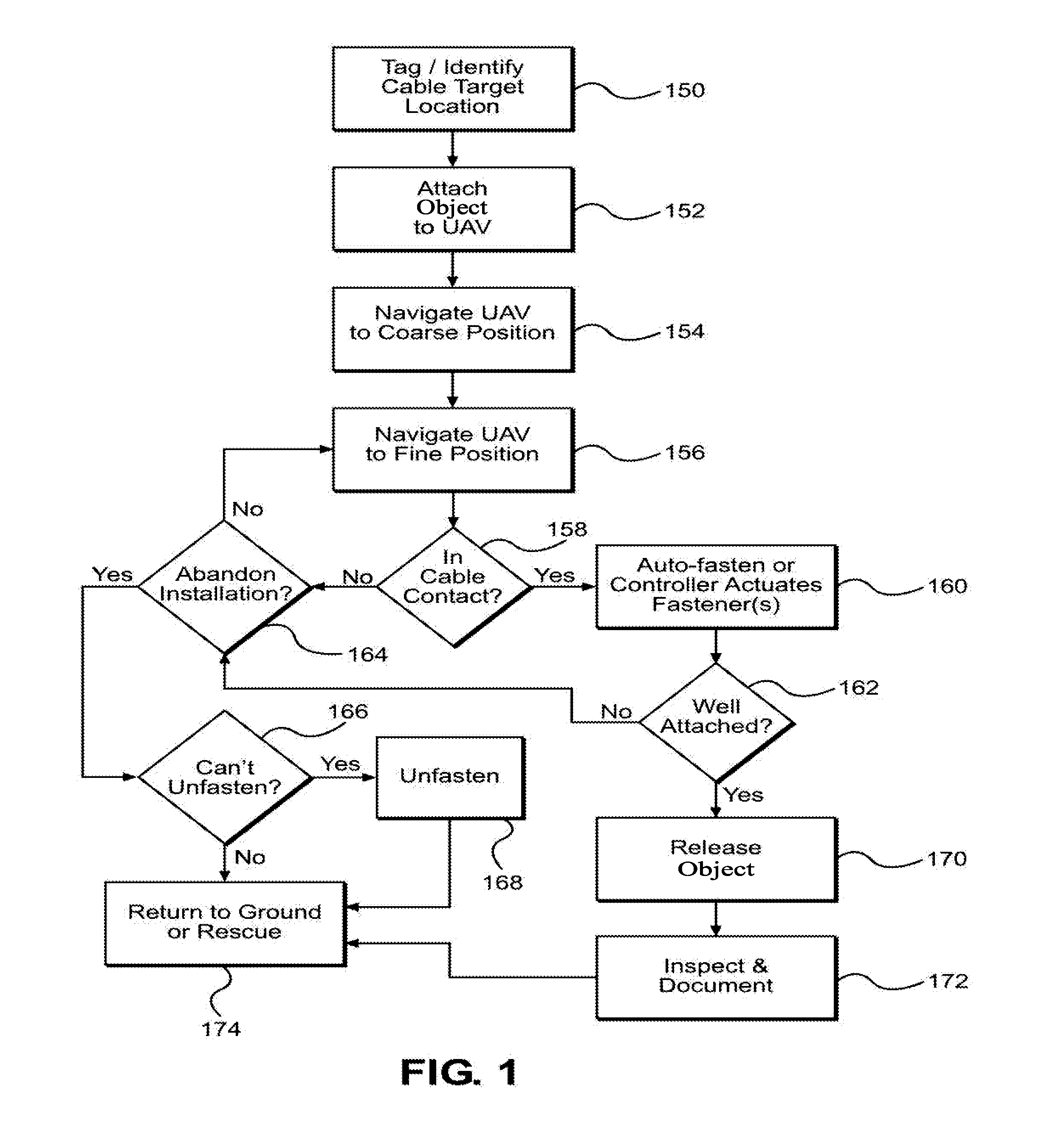
A method for using an unmanned aerial vehicle to install objects on wire and catenary structures is described. The method includes tagging the location, attaching the object to the UAV, navigating the UAV to the position, attaching the object, testing the attachment, releasing the object, inspecting the attachment, and returning the UAV to the ground. Sensors, flight control systems, means for attachment, and variations of embodiments of the methods, systems, and mechanical devices are described.

Description

[0001]This application claims the benefit of U.S. Provisional Patent Application No. 62 / 027,255, filed on Jul. 22, 2014, titled “Method For Installing An Aerial Marker Using An Unmanned Vehicle” which is incorporated by reference herein in its entirety for all purposes.FIELD OF THE INVENTION[0002]The present invention is in the technical field of aerial operations on utility infrastructures. More particularly, the present invention pertains to the field of installation of objects upon cables spans or catenary structures.DESCRIPTION OF RELATED ART[0003]Wires and cables are a major threat to low flying aircraft and birds. Due to the limitations of vision and the inconspicuous nature of wires, wires can be invisible until it is too late and a collision occurs, usually with disastrous results. Wires are particularly dangerous to helicopters; which, owing to their unique capabilities and mission requirements, often operate at low altitudes. Wire strikes are a leading cause of helicopter ...

Claims


Application Information

Patent Timeline
Patent Type & Authority Applications(United States)
IPC IPC(8): B64C39/02G05D1/12H02G7/00
CPCB64C39/024G05D1/12B64C2201/146B64C2201/024B64C2201/12H02G7/00G05D1/0094H02G1/02B64U2101/60B64U2201/20B64U70/30B64U10/13B64U2201/104B64U2101/30
Inventor MCNALLY, JONATHAN
Owner MCNALLY JONATHAN
Learn More