Pressure relief valve with singular body

a pressure relief valve and singular body technology, applied in the field of relief valves, can solve the problems of leakage at welding points, welding can add significantly to the complexity and cost of relief valve manufacture, and achieve the effect of reducing friction and galling

Active Publication Date: 2016-01-28
AUSCO
View PDF59 Cites 3 Cited by
  • Summary
  • Abstract
  • Description
  • Claims
  • Application Information

AI Technical Summary

Benefits of technology

[0014]The pin may include a coating configured to reduce friction and galling.
[0015]A pressure relief valve includes a singular body that encloses a seat and a stationary shim, a spring, within the singular body, that is at one end proximate to the shim and at another end proximate to a poppet, and a pin inserted into the pressure relief valve body that is configured to expand to lock the pressure relief valve into a housing bore. The stationary shim is immovably secured within the singular body, and the seat is fit into the singular body for receiving the poppet. The pin includes a coating configured to reduce friction and galling. The seat includes a non-threaded stepped region on its outer surface and the singular body includes a complementary stepped region on its inner surface such that when the seat is fit into the singular body. The stepped region of the seat and the complementary stepped region of the singular body interface with each other to prevent movement of the seat toward the spring.

Problems solved by technology

While modern welding techniques may be quite effective, the possibility still exists that leakage may occur at the welding points.
Moreover, welding can add significantly to the complexity and cost of relief valve manufacture.

Method used


Image

  • Pressure relief valve with singular body
  • Pressure relief valve with singular body
  • Pressure relief valve with singular body

Examples


Embodiment Construction

[0030]In describing the exemplary embodiments of the present disclosure illustrated in the drawings, specific terminology is employed for sake of clarity. However, the present disclosure is not intended to be limited to the specific terminology so selected, and it is to be understood that each specific element includes all technical equivalents which operate in a similar manner. In the drawings, the sizes of some components may be exaggerated for clarity.

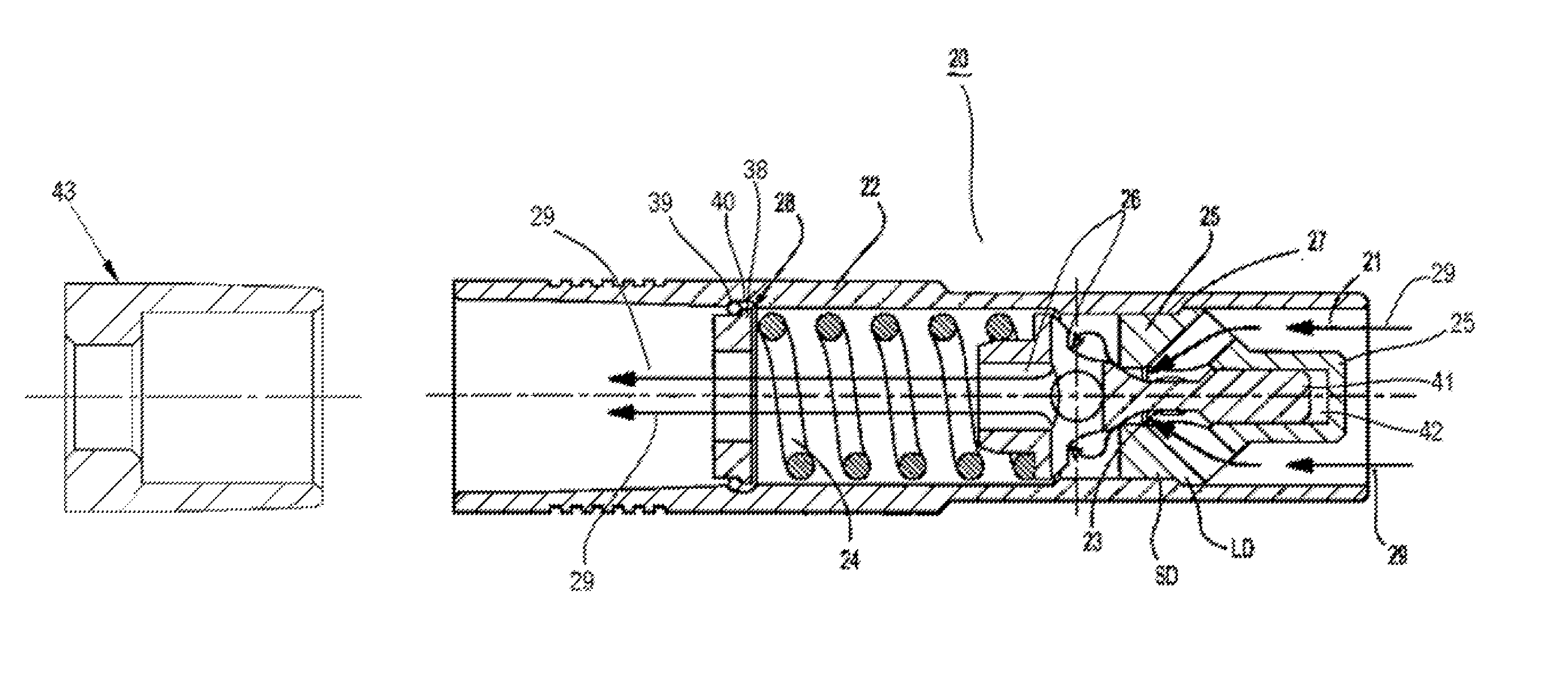
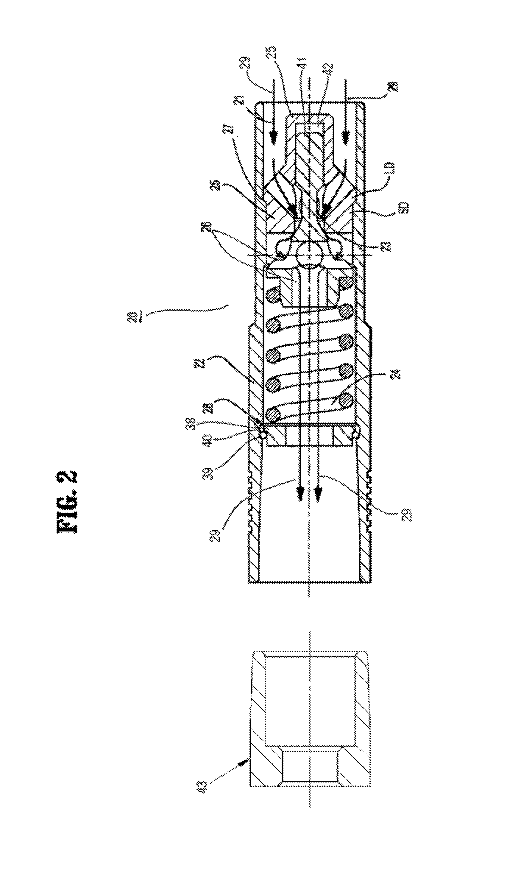
[0031]Exemplary embodiments of the present invention provide a pressure relief valve having a singular body including an inlet and an outlet, and enclosing a poppet, a seat, and a spring without the need for welding. Accordingly, pressure relief valves according to exemplary embodiments of the present invention may be more resistant to leaks and may be less expensive to manufacture than conventional pressure relief valves.

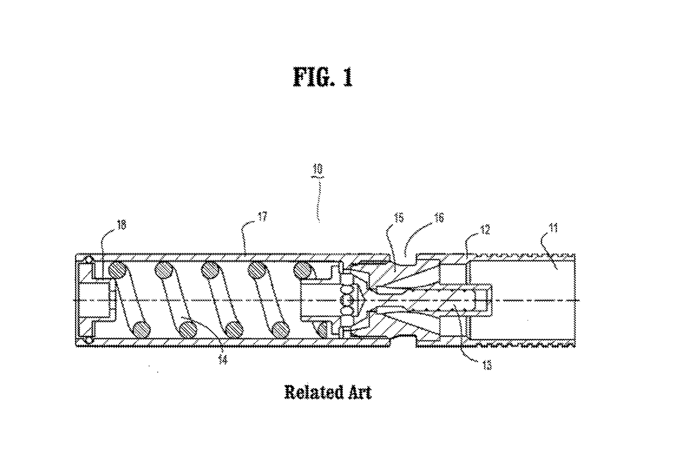
[0032]In conventional pressure relief valves, for example, as shown in FIG. 1, the seat 15 may be positioned bet...


PUM


Abstract

A pressure relief valve includes a singular body that encloses a seat and a stationary shim, a poppet, within the singular body, that is forced against a seat by a spring attached to the stationary shim, and a pin inserted into the pressure relief valve body to lock the pressure relief valve into a housing bore. The poppet includes a nose extension that extends into a void enclosed by the seat to provide damping. The seat includes a non-threaded stepped region on its outer surface and the singular body includes a complementary stepped region on its inner surface such that when the seat is fit into the singular body, the stepped region of the seat and the complementary stepped region of the singular body interface with each other to prevent movement of the seat toward the spring. The pin includes a coating to reduce friction and galling.

Description

CROSS REFERENCE TO RELATED APPLICATIONS[0001]This application is a divisional of U.S. application Ser. No. 14 / 063,760, of Francis J. Martin, filed on Oct. 25, 2013, in the U.S. Patent and Trademark Office, which in turn is a continuation-in-part of U.S. application Ser. No. 12 / 017,265, of Francis J. Martin, filed on Jan. 21, 2008, in the U.S. Patent and Trademark Office.BACKGROUND OF THE INVENTION[0002]1. Technical Field[0003]The present disclosure relates to a relief valve and, more specifically, to a pressure relief valve with a singular body.[0004]2. Discussion of the Related Art[0005]A relief valve is a type of valve used to control an amount of fluid pressure in a system. When pressure in the system rises to a predetermined level, the relief valve will open to allow the pressurized fluid to flow from an auxiliary passage out of the system. By releasing the pressurized fluid when the predetermined pressure is reached or exceeded, the system may be protected against excessive pre...

Claims


Application Information

Patent Timeline
Patent Type & Authority Applications(United States)
IPC IPC(8): F16K17/04F16K15/06F16K27/02
CPCF16K17/04F16K15/063F16K27/0209F16K17/10F16K17/196Y10T137/0497Y10T137/7758Y10T137/7854Y10T137/7939
Inventor MARTIN, FRANCIS, J.
Owner AUSCO
Why Eureka
Try Eureka