Refrigeration Circuit Control System

a refrigeration circuit and control system technology, applied in refrigeration components, mechanical equipment, lighting and heating equipment, etc., can solve problems such as reducing refrigeration circuit efficiency, and presenting risks in large-scale refrigerant applications such as toxic inhalation, fire and explosion, etc., to achieve efficient increase

Active Publication Date: 2016-01-28
DANFOSS LLC
View PDF5 Cites 9 Cited by
  • Summary
  • Abstract
  • Description
  • Claims
  • Application Information

AI Technical Summary

Benefits of technology

[0017]Disclosed is a refrigeration circuit control system that detects refrigerant state conditions and controls the circuit to increase efficiently and to regulate the quantity of working fluid needed to meet cooling load conditions, especially under transient cooling loads.
[0024]An advantage of installing a void-fraction sensor within the evaporator coil is that it allows the system to detect refrigerant liquid / vapor state discrepancies much earlier in the low side circuit line refrigerant flow path than installation of a sensor downstream of the evaporator coil. This allows for greatly improved system response times in controlling refrigerant flow to the evaporator.
[0026]In yet further embodiments, the system may use two sensors and adjust sensor set points for improved low side circuit performance. In such embodiments, when a first sensor located downstream of a second sensor detects an undesired refrigerant heat energy state, the first sensor provides a feedback signal to the system. The system responds by actuating the control valve appropriately and by adjusting the set point of the upstream second sensor to an appropriate level to obtain desired refrigerant heat energy state at the downstream location. In related embodiments, the system may adjust the set points for additional sensors located in the low side.

Problems solved by technology

Compressors are designed to compress only refrigerant gas and can be damaged if liquid refrigerant enters the compressor.
While configuring a refrigeration circuit to generate a set degree of superheat in refrigerant may be sufficient in steady-state cooling conditions, when evaporators are placed under variable cooling load conditions, operation errors can Occur.
Large superheat settings significantly reduce refrigeration circuit efficiency and require refrigeration circuits to flow large quantities of refrigerant.
While ammonia provides desired heat transferring properties, its use in large scale refrigerant applications presents risks including toxic inhalation, fire and explosion if there are refrigeration circuit or storage tank leaks.
As void fraction sensors can only detect quantities of liquid refrigerant present within the circuit they are unable to detect refrigerant superheat.
A limitation with evaluating low side refrigerant status with a void fraction sensor is that in any case of a refrigerant being at 0 degrees of superheat or above, the void fraction sensor's output remains null.
This leads to potential system inefficiently and malfunction, especially in changing transient cooling load conditions.
Another limitation with the above described refrigeration circuit control systems is that the superheat and void fraction sensors provide control feedback based on set superheat or liquid state refrigerant percentage values at the exit of an evaporator.
In variable cooling load conditions, feedback from a single sensor too slow to allow the system to properly meter control valve refrigerant flow to the low side.
This problem is heightened by sensors being installed downstream from the system evaporator.
By the time the void-fraction sensor provides an indication to the control system that refrigerant liquid content is too high or too low and corresponding valve actuation signals can be sent to the far upstream metering valve, it is too late to provide appropriate control of evaporator-downstream refrigerant vapor content.
In the case of too little refrigerant flow, this results in premature refrigerant over boiling within the evaporator, which decreases evaporator efficiently.
This adds to system installation costs and likewise lowers system efficiency.

Method used


Image

  • Refrigeration Circuit Control System
  • Refrigeration Circuit Control System
  • Refrigeration Circuit Control System

Examples


Embodiment Construction

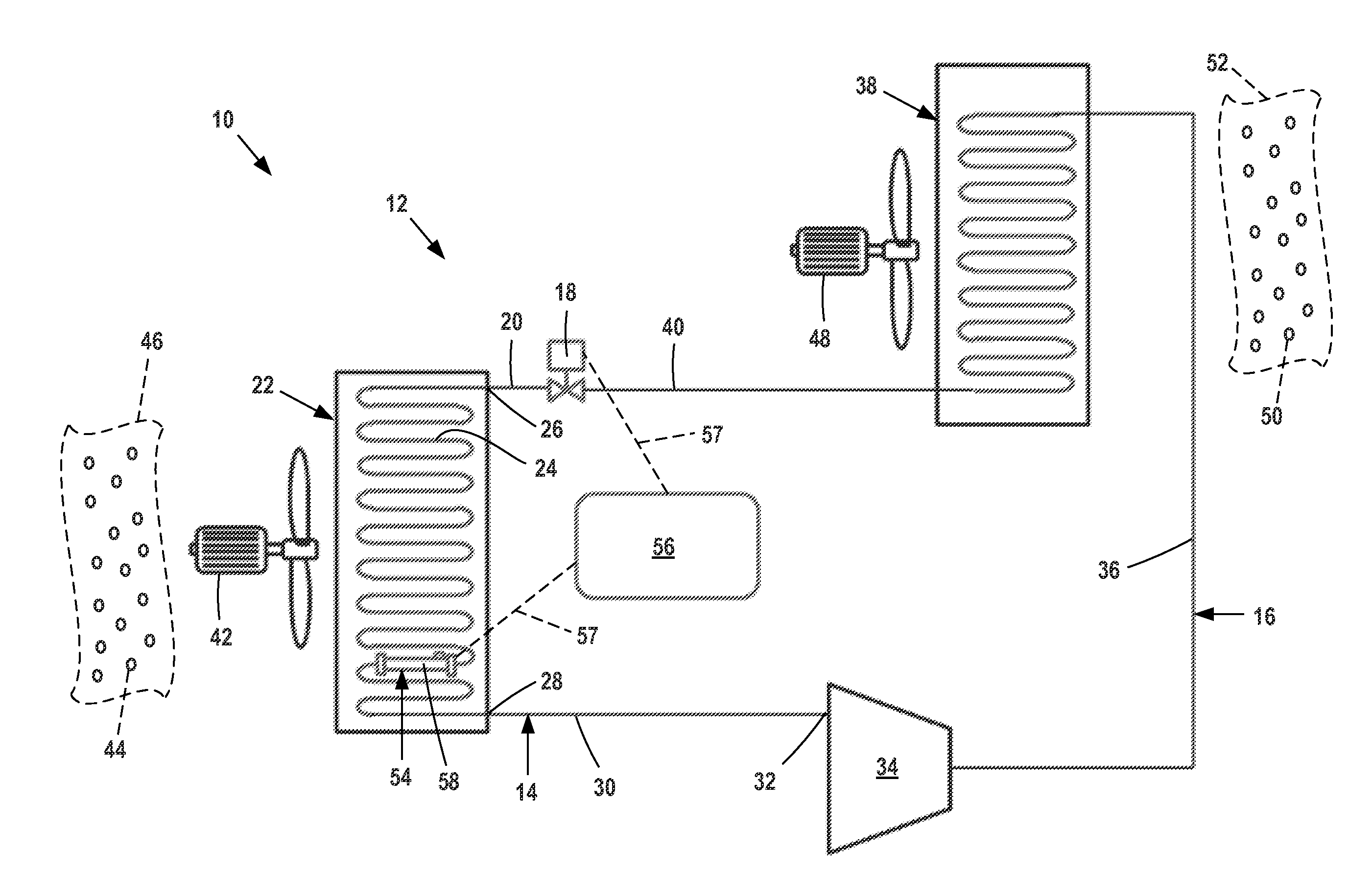
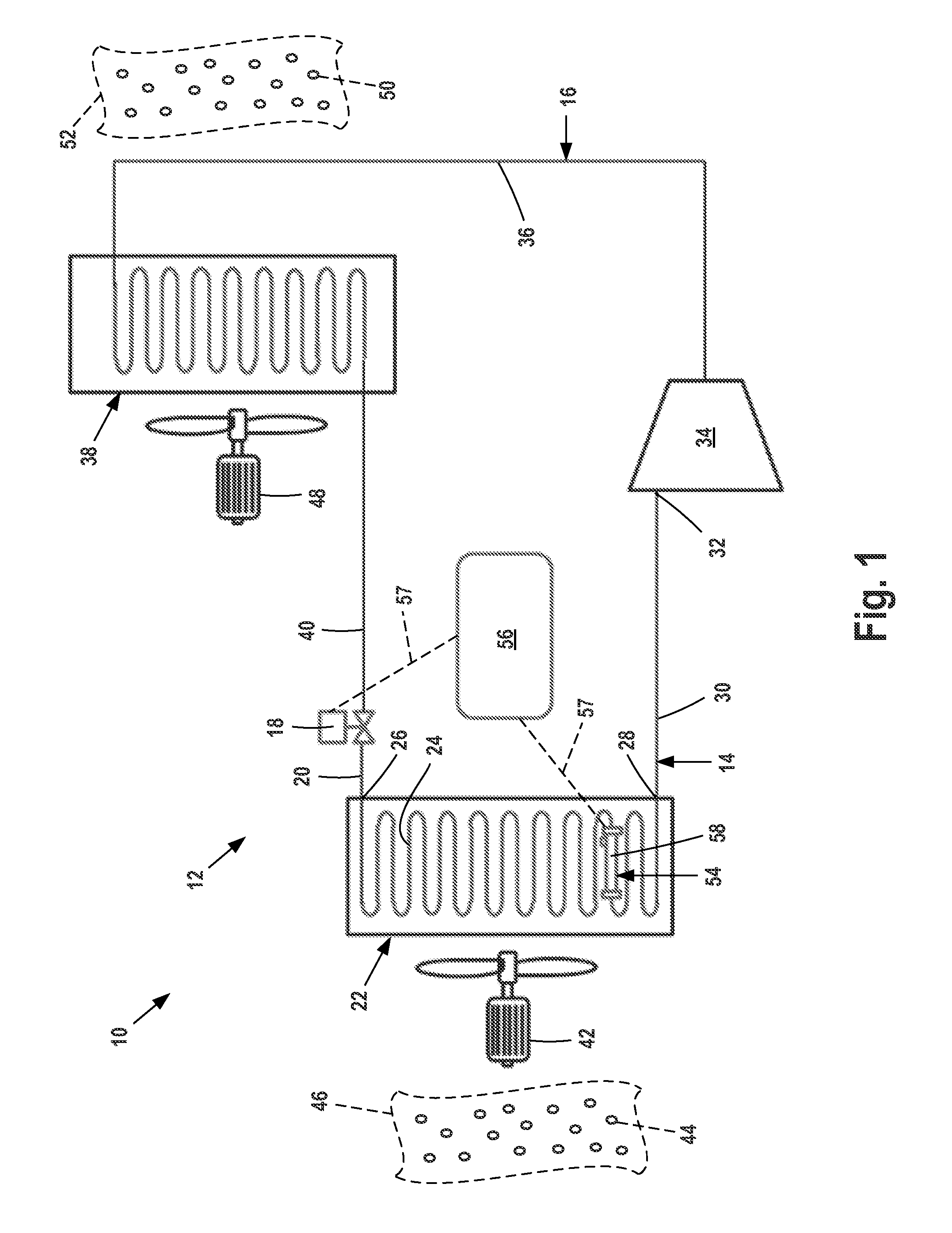
[0047]FIG. 1 is a representational view of a control system 10 for monitoring and controlling a refrigeration circuit 12.

[0048]Refrigeration circuit 12 includes circuit low pressure side or low side 14 and circuit high pressure side or high side 16.

[0049]Low side 14 and high side 16 are each made up of fluid lines and circuit components that circulate a working fluid refrigerant (not illustrated) during operation of refrigeration circuit 12.

[0050]Low side 14 extends from metering control valve 18 through evaporator input line 20 and through evaporator 22. Evaporator line 24 extends from evaporator inlet 26 to evaporator outlet 28. Low side 14 continues through evaporator output line 30 and ends at compressor inlet 32.

[0051]Metering control valve 18 may be a motorized expansion valve or like valve. Valve 18 is capable of being actuated electronically by a controller from a closed state to a desired degree of openness in order to control refrigerant flow through the valve at a desired...


PUM


Abstract

A control system for a refrigeration circuit having one or more working fluid refrigerant sensors capable of measuring the fluid energy value of the refrigerant along a low side of the refrigeration circuit and regulating the flow of refrigerant to the circuit low side through reference to expected refrigerant fluid energy values.

Description

FIELD OF THE DISCLOSURE[0001]The disclosure relates to the field of control systems for vapor-compression refrigeration circuits having a compressor, condenser and evaporator and more particularly to control systems for monitoring and controlling direct expansion (DX) evaporator refrigeration circuits.BACKGROUND OF THE DISCLOSURE[0002]Vapor-compression refrigeration circuits for circulating a working fluid refrigerant having a low side comprising an evaporator and a high side comprising a compressor and condenser are well-known.[0003]Refrigerant in a liquid state is metered to the low side of the refrigeration circuit by a metering control throttle valve. As the refrigerant flows through the low side evaporator, evaporator outlet line and other low side lines to the compressor, the refrigerant absorbs heat energy from the ambient environment. Heat energy absorbed by the refrigerant allows cooling of a desired space. As the refrigerant absorbs heat energy, it transforms from a liquid...

Claims


Application Information

Patent Timeline
Patent Type & Authority Applications(United States)
IPC IPC(8): F25B49/02F25B41/06
CPCF25B41/062F25B49/02F25B2700/00F25B2600/2513F25B2700/2117F25B2700/21175F25B2500/01F25B41/34Y02B30/70
Inventor MARSHALL, ARTHUR JAMESEBERLY, RANDY LYNN
Owner DANFOSS LLC
Why Eureka
Try Eureka