
Systems and methods for evaporative emissions testing

a technology of evaporative emissions and system, applied in the direction of measurement devices, instruments, structural/machine measurement, etc., can solve the problems of unfavorable maintenance and maintenance, inability to guarantee the stability of fuel temperature, and unnecessarily waste of stored battery charge at the wake of the pcm, so as to reduce the execution rate of leak test, reduce the number of false test results, and reduce the execution rate

Active Publication Date: 2016-01-28
FORD GLOBAL TECH LLC
View PDF8 Cites 10 Cited by
  • Summary
  • Abstract
  • Description
  • Claims
  • Application Information

AI Technical Summary

Benefits of technology

The patent describes a system and method for performing a leak test on a vehicle's fuel system. The system includes a powertrain control module that is responsible for waking up the vehicle after it has been turned off. The leak test is initiated based on the temperature of the fuel tank and the ambient temperature. By waking up the control module at a specific time, the system can ensure that the fuel tank is stable and the conditions for the leak test are met. This method helps to increase the accuracy of the leak test and avoid false failures, while conserving battery charge and reducing wear and tear on fuel system valves.

Problems solved by technology

Hybrid vehicles and other vehicles with inherently low manifold vacuum may perform leak tests while the vehicle is turned off.
Waking the PCM at an arbitrary time following the vehicle off condition does not guarantee that the fuel temperature will be stable, or that other conditions for a leak test are met.
Waking the PCM unnecessarily wastes stored battery charge.
Executing the leak test at during inopportune conditions may cause false failures that impact the test efficacy.
Further, initiating a leak test that will be aborted may involve cycling system valves open and closed, reducing their expected lifespan.
At an arbitrary time point, changes in weather following the vehicle-off event may lead to a failure to meet testing entry conditions, thus reducing the execution rate of the leak test.

Method used


Image

  • Systems and methods for evaporative emissions testing
  • Systems and methods for evaporative emissions testing
  • Systems and methods for evaporative emissions testing

Examples


Embodiment Construction

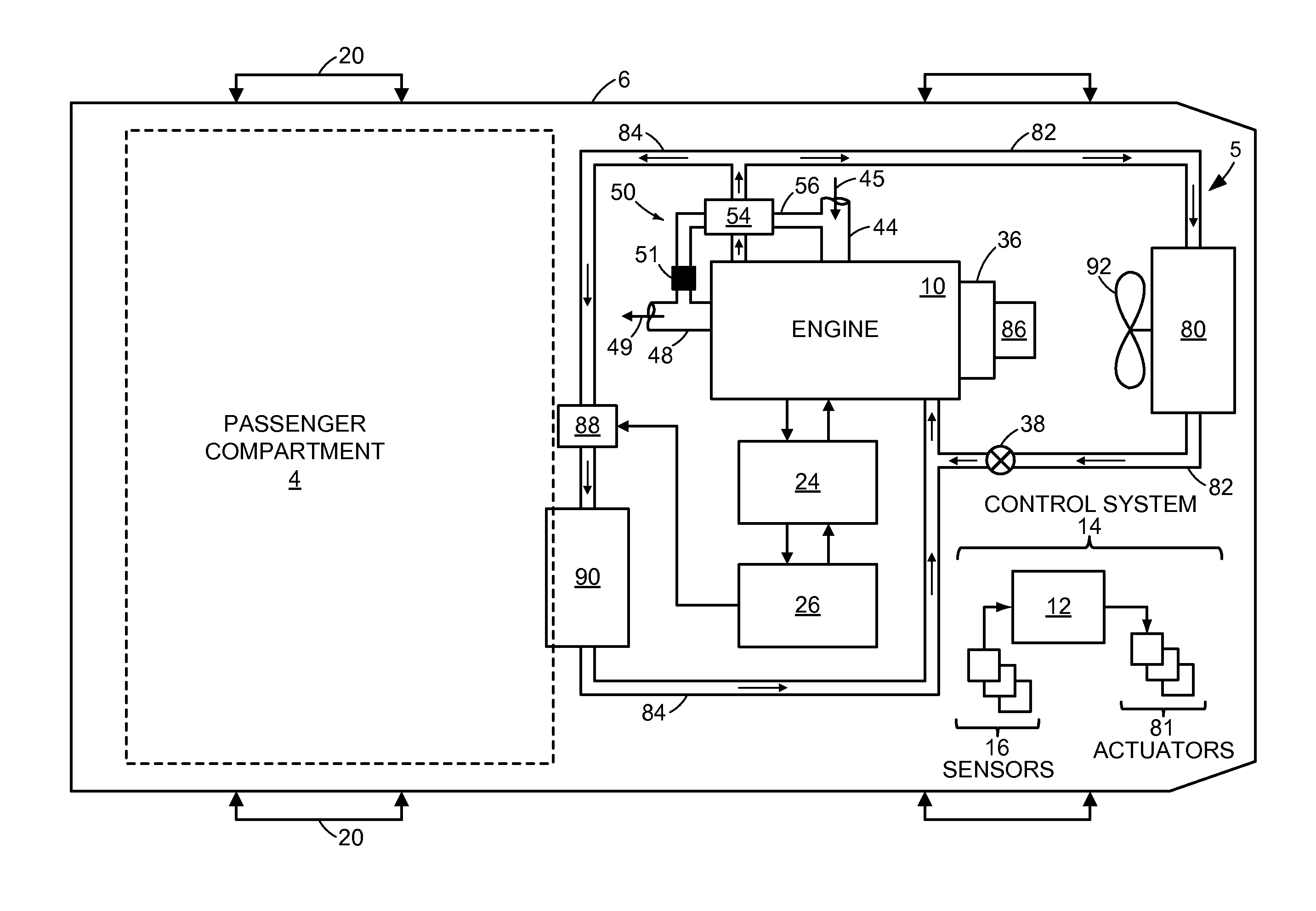
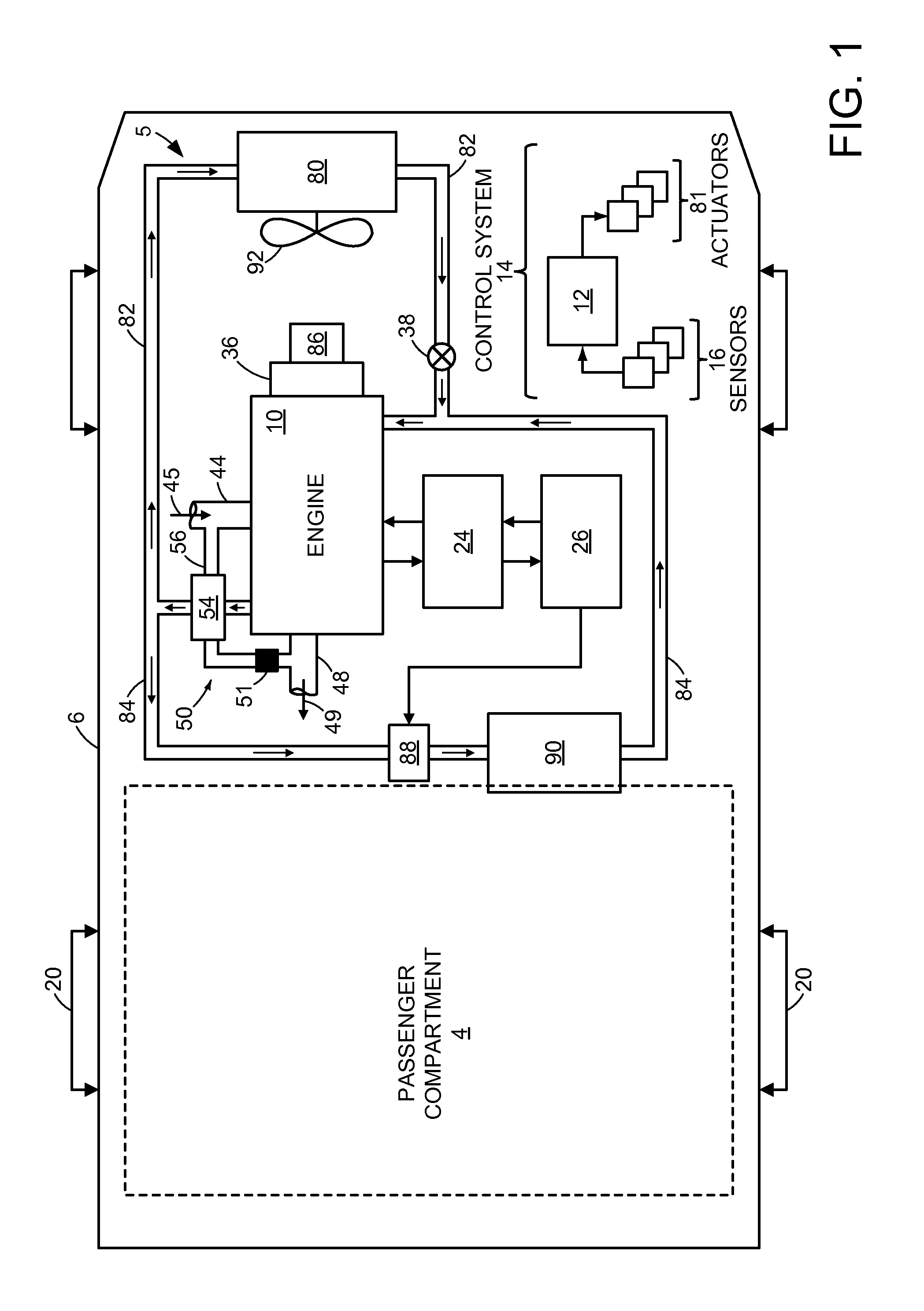
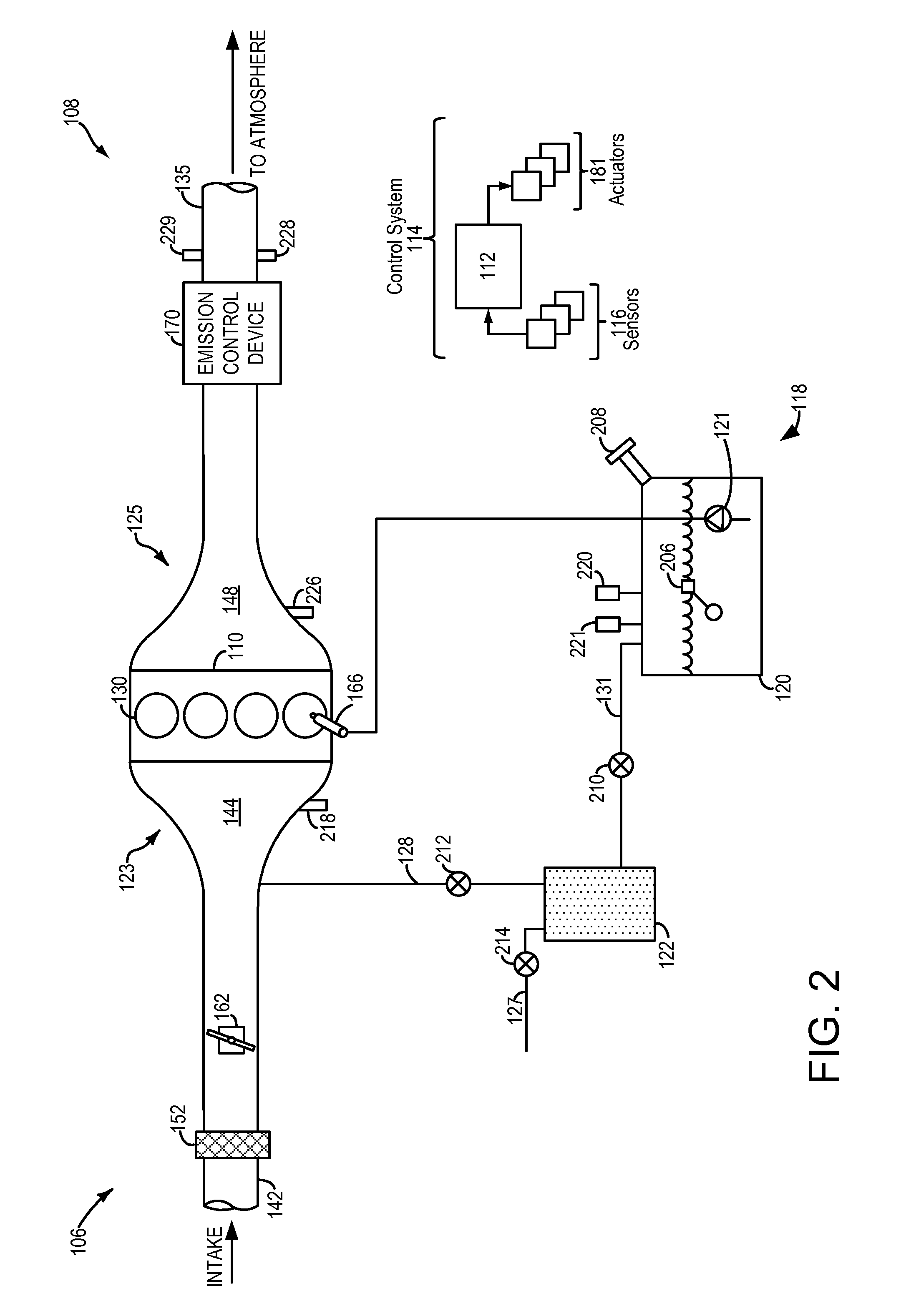
[0014]This detailed description relates to systems and methods for performing a leak test for a vehicle fuel system. In particular, this description relates to systems and methods for initiating a leak test by waking a powertrain control module when a bulk fuel temperature is within a threshold of an ambient temperature. The vehicle may include a coolant system, as depicted in FIG. 1 as well as an evaporative emissions system, as depicted in FIG. 2. The powertrain control module may comprise a wake input coupled to a comparator circuit, as depicted in FIG. 3. The comparator circuit may be configured to indicate a ratio of bulk fuel temperature to ambient temperature, allowing for the powertrain control module to initiate a leak test when the ratio decreases below a threshold. FIG. 4 depicts a flow chart for a method for an evaporative emissions test using the systems of FIGS. 1-3. FIG. 5 depicts a timeline for an example evaporative emissions test utilizing the method of FIG. 4.

[001...


PUM


Abstract

A method for a vehicle, comprising: following a vehicle-off event, waking a powertrain control module based on a comparison of an ambient temperature and a bulk fuel temperature; and then initiating an evaporative emissions system leak test. In this way, the evaporative emission leak test may be initiated without waking the powertrain control module arbitrarily. By waking the powertrain control module and initiating the test based on ambient and bulk fuel temperatures the execution rate of the leak test can be increased.

Description

BACKGROUND AND SUMMARY[0001]Vehicle emission control systems may be configured to store fuel vapors from fuel tank refueling and diurnal engine operations, and then purge the stored vapors during a subsequent engine operation. In an effort to meet stringent federal emissions regulations, emission control systems may need to be intermittently diagnosed for the presence of leaks that could release fuel vapors to the atmosphere.[0002]Hybrid vehicles and other vehicles with inherently low manifold vacuum may perform leak tests while the vehicle is turned off. In some examples, the leak test is based on natural pressure or vacuum that occurs in the fuel tank due to fuel heating or cooling. In some examples, the fuel system may include a vacuum pump configured to draw a vacuum on the fuel tank and evaporative emissions system. In order to increase the accuracy of the leak test, the test may be initiated at a time point following vehicle shut-off, thus allowing for the bulk fuel temperatur...

Claims


Application Information

Patent Timeline
IPC IPC(8): G01M3/02G01K13/02
CPCG01K13/02G01M3/025G01K3/14
Inventor DUDAR, AED, M.
Owner FORD GLOBAL TECH LLC
Learn More