Smart network system

a network system and smart technology, applied in the field of smart network systems, can solve the problems of restricting functions and deteriorating overall integrity, and achieve the effects of improving the overall integrity, overall integrity of the outlook of the slide-on-strap touch-sensing structure, and enhancing the functions possessed

Inactive Publication Date: 2016-01-28
HANNSTAR DISPLAY NANJING +1
View PDF9 Cites 1 Cited by
  • Summary
  • Abstract
  • Description
  • Claims
  • Application Information

AI Technical Summary

Benefits of technology

[0008]An aspect of the invention is to provide a smart network system applied to communication between an addressing wireless display device and a smart slide-on-strap terminal device to increase the applications of the smart slide-on-strap terminal device and even enhance the functions of the smart slide-on-strap terminal device by the smart network system, and to facilitate the overall integrity of the outlook of the smart slide-on-strap terminal device by disposing the slide-on-strap touch-sensing structure on the smart slide-on-strap terminal device. In details, the smart slide-on-strap terminal device has the slide-on-strap touch-sensing structure, which has the touch input function and is disposed on the strap, and a processing unit produces the corresponding operation instruction according to the user's input. A wireless module transmits the operation instruction to the addressing wireless display device to remotely control the electronic device, and to enhance the functions possessed by the smart slide-on-strap terminal device. Meanwhile, the design of the slide-on-strap touch-sensing structure can further need no more physical buttons, so that the overall integrity of the outlook of the slide-on-strap touch-sensing structure is maintained.
[0029]In summary, the user can perform the touch input by operating the smart slide-on-trap touch sensing terminal device to communicate with the addressing wireless display device. The user can perform the touch operation on the slide-on-strap touch-sensing structure disposed on the strap. Next, the processing unit produces the corresponding operation instruction, and the wireless module transmits the operation instruction to the addressing wireless display device to remotely control the addressing wireless display device. In other words, the smart slide-on-strap terminal device may be used as the smart remote controller to enhance the functions possessed by the smart slide-on-strap terminal device. The design of the slide-on-strap touch-sensing structure may also need no more physical buttons, and the overall integrity of the outlook of the slide-on-strap touch-sensing structure can be maintained. In addition, because the element of performing the touch operation is the slide-on-strap touch-sensing structure, the conventional physical button can be replaced, and the overall integrity and beauty of the outlook of the smart slide-on-strap terminal device can be upgrade, and the higher quality and more wonderful user experience can be achieved.

Problems solved by technology

However, either the smart watch or the smart bracelet has the small size, and thus has the restricted functions.
In details, most input functions of the wearable smart device are executed through physical buttons, and the physical buttons need to be additionally disposed on the surface of the wearable smart device, thereby deteriorating the overall integrity

Method used


Image

  • Smart network system
  • Smart network system
  • Smart network system

Examples


Embodiment Construction

[0040]The embodiments of the invention will be apparent from the following detailed description, which proceeds with reference to the accompanying drawings, wherein the same references relate to the same elements.

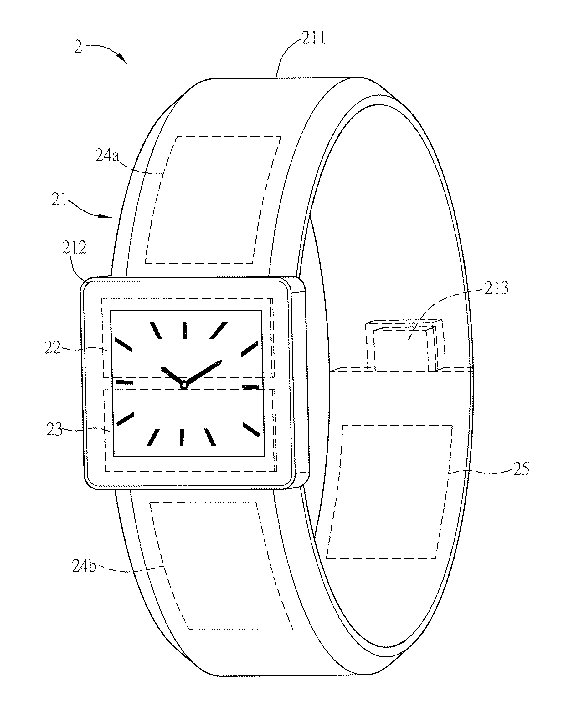
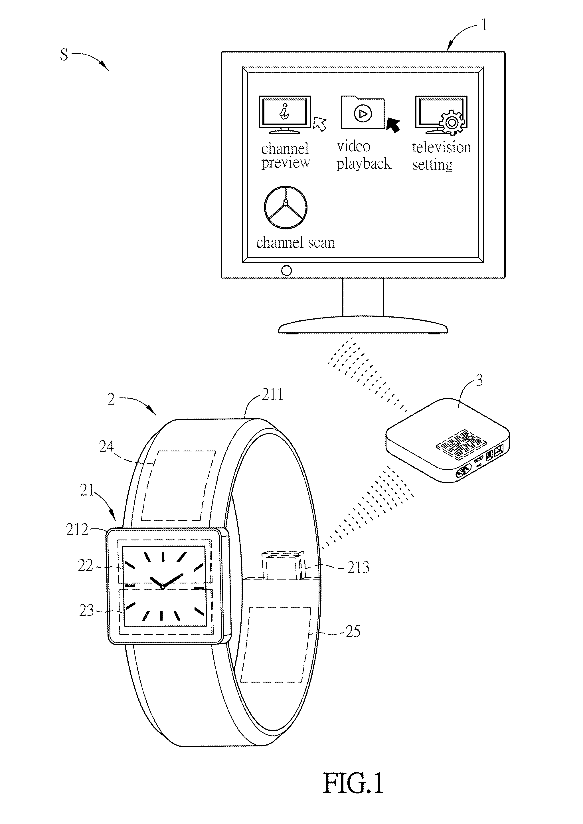
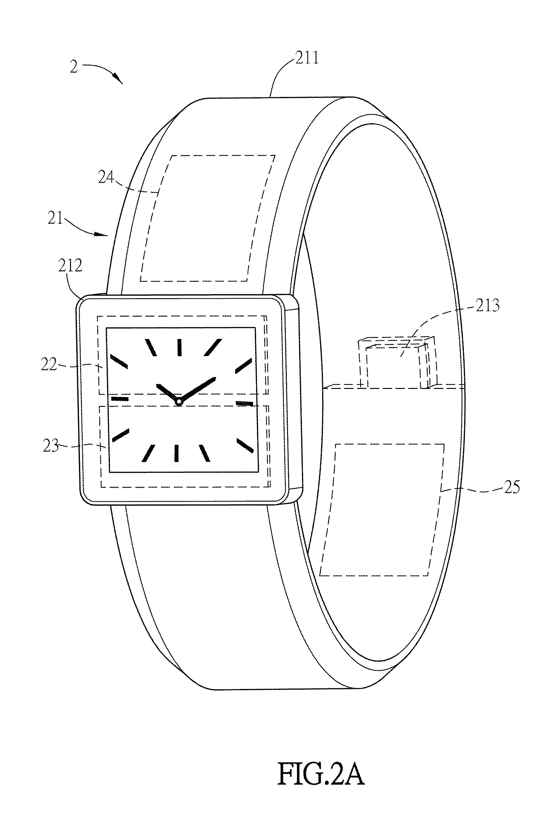
[0041]FIG. 1 is a schematic diagram showing the smart network system according to an embodiment of the invention. Referring to FIG. 1, the smart network system S comprises at least one addressing wireless display device 1 and a smart slide-on-strap terminal device 2. In the embodiment, the addressing wireless display device 1 is a display device having fixed domain name and position. In general, it is disposed at a stationary location and regarded as stationary display screen which is distinguish from the display screen of the hand-held electronic device (for example, mobile phone, tablet computer, etc.). The smart slide-on-strap terminal device 2 in the embodiment is applied to a wearable device, which may be directly worn by the user, and may comprise a smart bracelet, a ...


PUM


Abstract

A smart network system comprises at least one addressing wireless display device and a smart slide-on-strap terminal device. The smart slide-on-strap terminal device communicates with the addressing wireless display device. The smart slide-on-strap terminal device comprises a body, a wireless module, a processing unit, and at least one slide-on-strap touch-sensing structure. The body has a strap. The wireless module is disposed on the body. The processing unit is coupled to the wireless module. The slide-on-strap touch-sensing structure is disposed on the strap and coupled to the processing unit. The slide-on-strap touch-sensing structure senses at least one trigger event to remotely control the addressing wireless display device. The disclosure is applied to the communication between the addressing wireless display device and the smart slide-on-strap terminal device to increase the applications of the smart slide-on-strap terminal device.

Description

CROSS REFERENCE TO RELATED APPLICATIONS[0001]This Non-provisional application claims priority under 35 U.S.C. §119(a) on Patent Application No(s). 201410360833.9 filed in People's Republic of China on Jul. 25, 2014, the entire contents of which are hereby incorporated by referenceBACKGROUND[0002]1. Technical Field[0003]The invention relates to a smart network system, in particular to a smart network applied to between an addressing wireless display device and a smart slide-on-strap terminal device.[0004]2. Related Art[0005]With the progress of technologies, various information devices having communication functions are continuously innovated, such as mobile phones, tablet computers, ultra-thin notebook computers, satellite navigation devices or the like. At present, due to advances in technology, the processors are continuously developed to be smaller size and the higher performance. Thus some wearable devices having the sizes much smaller than other communication devices are also d...

Claims


Application Information

Patent Timeline
Patent Type & Authority Applications(United States)
IPC IPC(8): G06F3/14G06F3/044G06F3/0484G06F3/0485G06F3/0488H04W4/80
CPCG06F3/14G06F3/044G06F3/0488G06F3/0485G06F3/04842H04W4/008G06F3/1423G06F3/1454G09G2370/16G06F1/163G06F1/169G06F3/038G06F2203/0339G06F2203/0383G06F2203/0384G06F3/04883G06F3/04847G06F3/03547G04R20/26H04W4/80
Inventor WU, HSU-HOLU, TIEN-RONG
Owner HANNSTAR DISPLAY NANJING
Why Eureka
Try Eureka