Heater and image heating apparatus including the same
a heating apparatus and image technology, applied in the field of heaters and image heating apparatus including the same, can solve the problem of a larger amount of electric power consumption, and achieve the effect of suppressing electric power consumption
- Summary
- Abstract
- Description
- Claims
- Application Information
AI Technical Summary
Benefits of technology
Problems solved by technology
Method used
Image

Examples
embodiment 1
Image Forming Portion
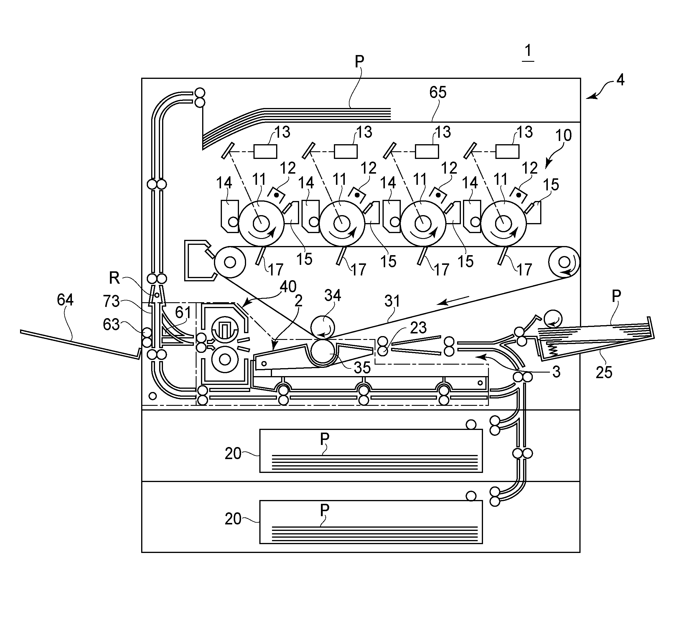
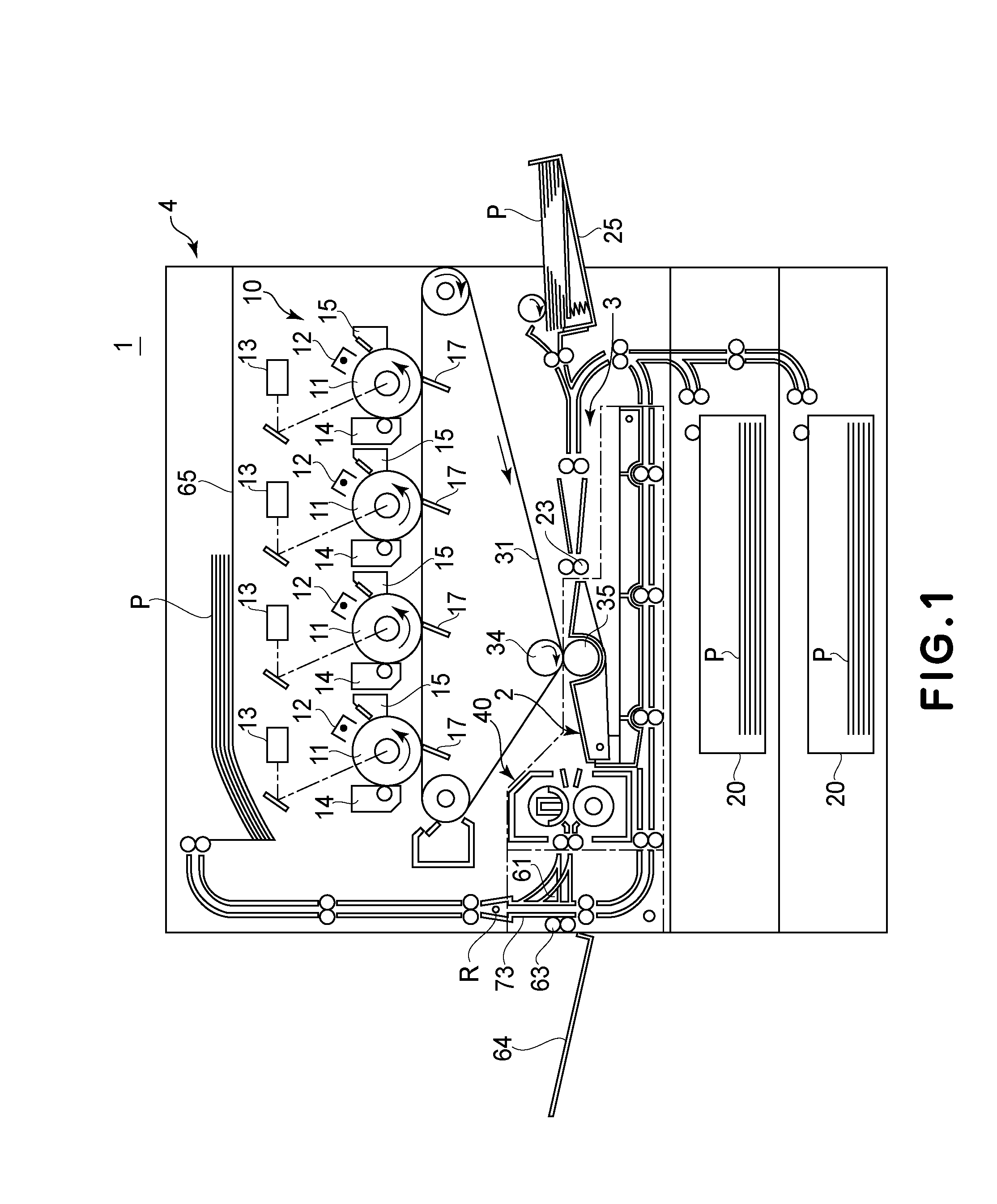
[0027]FIG. 1 is a sectional view of the printer 1 which is the image forming apparatus of this embodiment. The printer 1 comprises an image forming station 10 and a fixing device 40, in which a toner image formed on the photosensitive drum 11 is transferred onto a sheet P, and is fixed on the sheet P, by which an image is formed on the sheet P. Referring to FIG. 1, the structures of the apparatus will be described in detail.
[0028]As shown in FIG. 1, the printer 1 includes image forming stations 10 for forming respective color toner images Y (yellow), M (magenta), C (cyan) and Bk (black). The image forming stations 10 includes respective photosensitive drums 11 (11Y, 11M, 11C, 11Bk) corresponding to Y, M, C, Bk colors are arranged in the order named from the left side. Around each drum 11, similar elements are provided as follows: a charger 12 (12Y, 12M, 12C, 12Bk); an exposure device 13 (13Y, 13M, 13C, 13Bk); a developing device 14 (14Y, 14M, 14C, 14Bk); a prima...
embodiment 2
[0121]A heater according to Embodiment 2 of the present invention will be described. FIG. 12 illustrates a structure of a heater 600 in this embodiment. FIG. 13 is an illustrates an effect in this embodiment. In Embodiment 1, the line width of the electroconductive line 640 is made thick compared with the line width of the electroconductive lines 650, 660. On the other hand, in Embodiment 2, in addition to the constitution of Embodiment 1, the line width of the electroconductive line 650 is made thick compared with the line width of the electroconductive line 660. Specifically, this is because the number of the heat generating elements 620 connected with the electroconductive line 650 is larger than the number of the heat generating elements 620 connected with the electroconductive line 660 and an amount of the current flowing through the electroconductive line 650 is large compared with an amount of the current flowing through the electroconductive line 660. Further, the heater in ...
embodiment 3
[0140]A heater according to Embodiment 3 of the present invention will be described. FIG. 12 illustrates a structure of a heater 600 in this embodiment. FIG. 13 is an illustrates an effect in this embodiment. FIG. 16 illustrates a state of a temperature distribution of the heater 600 in each of Embodiment 3 and Comparison Example 1. In FIG. 17, (a) illustrates a constitution of a first modified embodiment, and (b) illustrates a constitution of a second modified embodiment.
[0141]In Embodiment 1, the line width of the electroconductive line 640 is made thick compared with the line width of the electroconductive lines 650, 660. In Embodiment 3, in addition to the constitution of Embodiment 2, the line width of the electroconductive line 660b is made thick compared with the line width of the electroconductive line 660a.
[0142]Specifically, a length of a path of the electroconductive line 660b connecting the electrical contact 661b and the heat generating elements 620k, 620l is longer th...
PUM
 Abstract
Description
Claims
Application Information
 - R&D
- Intellectual Property
- Life Sciences
- Materials
- Tech Scout
- Unparalleled Data Quality
- Higher Quality Content
- 60% Fewer Hallucinations
Browse by: Latest US Patents, China's latest patents, Technical Efficacy Thesaurus, Application Domain, Technology Topic, Popular Technical Reports.
© 2025 PatSnap. All rights reserved.Legal|Privacy policy|Modern Slavery Act Transparency Statement|Sitemap|About US| Contact US: help@patsnap.com