Road for charging electric vehicle

a charging electric vehicle and electric vehicle technology, applied in the field of roads, can solve the problems of inability to charge for a long time, insurmountable problems of electric vehicles, endurance ability, etc., and achieve the effect of reducing the possibility of electric leakage and improving the cruising ability of electric vehicles

Active Publication Date: 2016-02-04
LI KA FAT +1
View PDF5 Cites 7 Cited by
  • Summary
  • Abstract
  • Description
  • Claims
  • Application Information

AI Technical Summary

Benefits of technology

[0024]According to the present invention, the road surface is provided with electrified rail, and the electric vehicle can charge by means of inserting its electric plate into the electrified rail and keep driving with the electric plate. Thus the electric vehicle can charge while driving, thereby improving the cruising ability of the electric vehicle. In addition, the electrified rail is provided with insulated cover so as to avoid accidents of electric shock and prevent the rainwater from entering into the electrified rail, and then reduce the possibility of electric leakage.

Problems solved by technology

Climatic variation, energy and environmental problem are common problems always faced by all of people in the society.
However, the electric vehicles have some insurmountable problems, one of which is endurance ability.
The conventional ICE vehicles can move ahead immediately as long as fill up the gas tank, but the electric vehicles need more time to charge, which has definitely hindered the widespread application of the electric vehicles.
The third rail was applied high voltage of 700V to 1500V, thus it brought a big hidden danger and it caused many electric shock accidents for years.
In USA, it was proposed that a cover was added onto the rail but such a solution still cannot solve the safety problem.
But the above method is not suitable for the regular road due to its rough surface.
And in China, it was proposed that high-voltage live wires were exposed on the ground and connected with the vehicles on the road (shown in FIG. 2), but it was very dangerous.
Such a solution is successful for sunny day, but once a rainy day comes, all of the electrodes will contact with the raining water on the road, which then leads to a trip or the electric power being used for electrolysis of water and which also brings dangers to people on the road.
However, the harm to the people caused by such a structure was under study and it could not be popularized.
Recently, a lot of charging posts are rising around the world, however, the charging times of which are still dissatisfying, and most of the charging posts are disposed outside so that they are not suitable for use on a rainy day.

Method used


Image

  • Road for charging electric vehicle
  • Road for charging electric vehicle
  • Road for charging electric vehicle

Examples


first embodiment

[0039]The

[0040]FIG. 5 to FIG. 8 illustrate the detailed structure of the present invention according to the first embodiment.

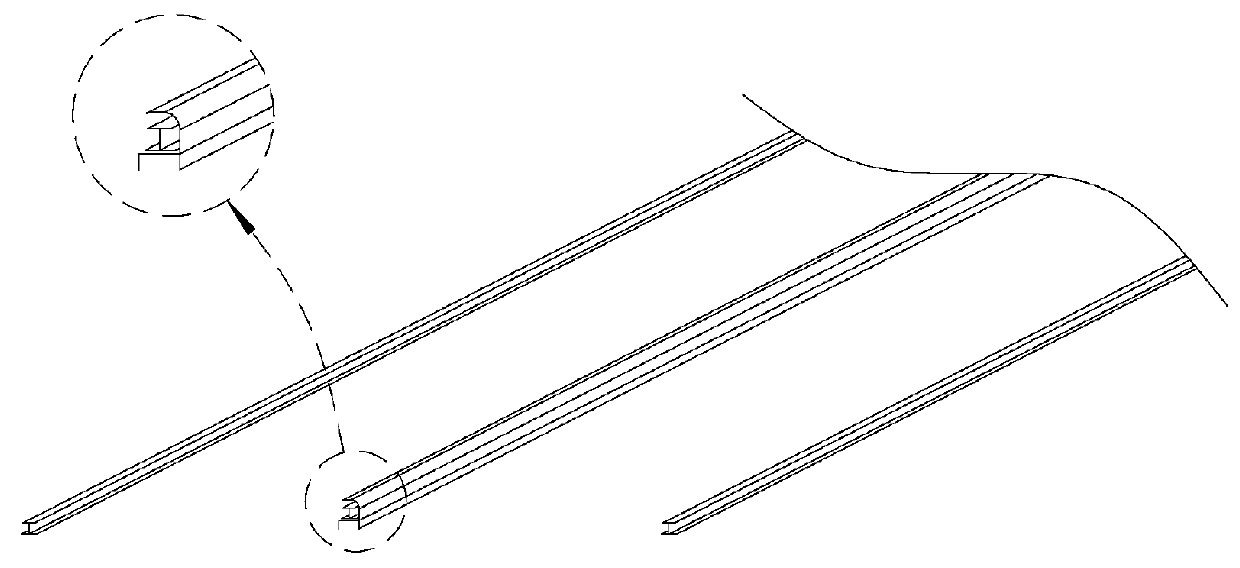
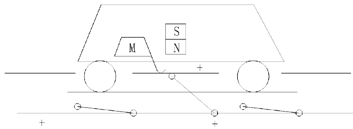
[0041]According to the first embodiment, the road for charging electric vehicle includes road surface 100, light posts on the road surface 100 and electrified rail 10 placed along a driving direction and provided for charging the electric vehicle while driving. The first embodiment is mainly applied on electric cars.

[0042]The electrified rail 10 includes electrode plate for connecting electric plate 21 of the electric vehicle 30 and insulated cover 13 covering on the plate electrode so as to prevent electric leakage. The electrode plate includes first electrode plate 11 and second electrode plate 12. The first electrode plate 11 connects to live wire of electric supply and the second electrode plate 12 connects to neutral wire of electric supply. The first electrode plate 11 is placed above the second electrode plate 12 and between the first electrode plate 11...

second embodiment

[0049]The

[0050]FIG. 9 and FIG. 10 illustrate the detailed structure of the present invention according to the second embodiment. Compared with the first embodiment, the second embodiment has following different structure: the electrified rail 40 has two sets of electrode plates 41 which can electrically connect to two electric plates 51 of the same electric vehicle, respectively, thereby increasing the charging current and then shortening the charging time.

[0051]In other embodiment, the two sets of electrode plates are electrically connected to two electric plates of two electric vehicles driving in opposite direction, respectively. Only one electrified rail is needed to charge the electric vehicles driven on both sides of the electrified rail, thereby reducing the cost. At the same time, such an electrified rail can meet the requirements of driven on the left system and driven on the right system.

[0052]In other embodiment, the two sets of electrode plates are electrically connected...

fourth embodiment

[0056]The

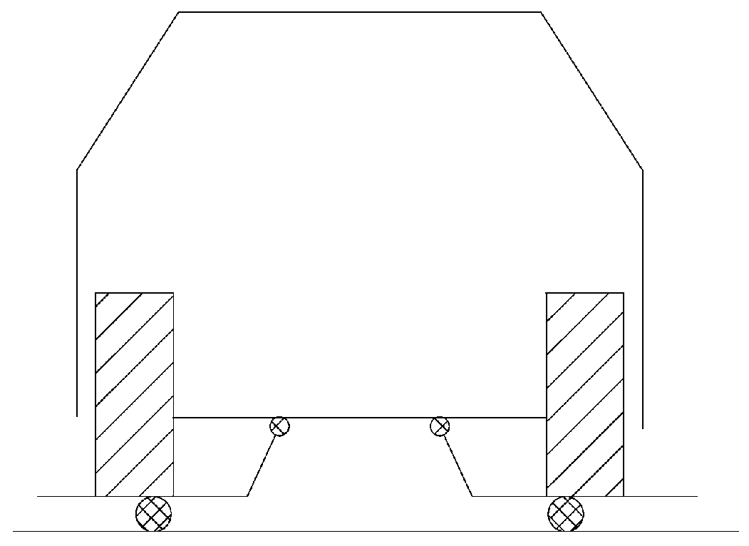
[0057]FIG. 15 to FIG. 16 show a detailed structure of the fourth embodiment which is mainly applied on large vehicles, such as buses. Compared with the first embodiment, the fourth embodiment has following different structure: the electrified rail 82 is placed between two adjacent light posts 81 on the road surface 800 and fixed on a higher position thereof. According to the fourth embodiment, the electrified rail 82 could be placed only on the light posts 81 which are close to the crossroads for charging of the large vehicles stopped at a red light. In other embodiments, the electrified rails 82 are continuously placed on all of the light posts 81 on the road 800, thus the electric vehicle can charge during driving.

[0058]As shown in FIG. 15, the large vehicle 90 connects with the electric plate 93 via a retracted mechanical arm which includes a short arm 91 and a long arm 92. The long arm 92 is rotatably attached to the short arm 91 and the short arm 91 is rotatably attach...


PUM


Abstract

Disclosed is a road for charging electric vehicle. The road includes an electrified rail which includes an electrode plate for connecting an electric plate of the electric vehicle, an insulated cover covering on the plate electrode so as to prevent electric leakage and a neutral layer covering on the insulated cover for connecting a neutral electrode plate of the electric vehicle. The electrode plate includes a first electrode plate and a second electrode plate. The first electrode plate is disposed above the second electrode plate and between the first electrode plate and the second electrode plate there is a gap so that the electric plate of the electric vehicle is able to be sandwiched between the first electrode plate and the second electrode plate while charging. According to the present invention, the road surface is provided with electrified rail, thus the electric vehicle can charge while driving.

Description

CROSS-REFERENCE TO RELATED APPLICATIONS[0001]This present invention claims the benefit of Chinese Patent Application No. 201420422312.7, filed on Jul. 29, 2014, the contents of which are hereby incorporated by reference.FIELD OF THE INVENTION[0002]The present invention relates to roads, and more particularly to a road for charging electric vehicle.BACKGROUND OF THE INVENTION[0003]Climatic variation, energy and environmental problem are common problems always faced by all of people in the society. As America returns to COP15 (the 15th meeting of contracting party of UN Framework Convention on Climate Change) and the emerging countries, which are represented by China and India, are included, and the main countries aggressively implement the strategy of energy saving and environment protection, the world has entered a new era for solving the common problems always faced by all of people in the society. Greenhouse gas emission, energy consumption and exhaust gas emission are the top thr...

Claims


Application Information

Patent Timeline
Patent Type & Authority Applications(United States)
IPC IPC(8): B60L11/18
CPCB60L11/1816B60L11/1824B60L5/40B60L5/38B60L5/39B60M1/34B60L53/14B60L53/30Y02T10/70Y02T90/12Y02T10/7072Y02T90/14
Inventor LI, KA FATPUN, KWOK WAH
Owner LI KA FAT
Why Eureka
Try Eureka