Remote-controlled crane

a remote control and crane technology, applied in the field of cranes, can solve the problems of unsolved above-named problems, skewed rotational axes of the joystick of the remote control, and requiring some practi

Active Publication Date: 2016-02-04
LIEBHERR WERK BIBERACH
View PDF23 Cites 33 Cited by
  • Summary
  • Abstract
  • Description
  • Claims
  • Application Information

AI Technical Summary

Benefits of technology

[0008]The object of the present disclosure therefore is to provide an improved crane of the kind described above, which does not have the disadvantages of the state of...

Problems solved by technology

However, operating the remote control requires some practice, since depending on where the crane operator stands with the remote control in relation to the crane, the rotational axes of the joystick of the remote control can be skewed in relation to the actual axes of movement...

Method used


Image

  • Remote-controlled crane
  • Remote-controlled crane
  • Remote-controlled crane

Examples


Embodiment Construction

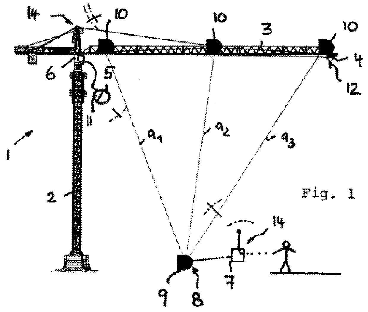
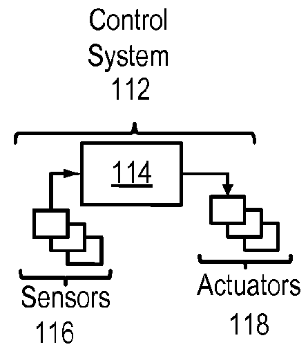
[0022]As FIG. 1 shows, crane 1 can be designed as a tower crane whose tower 2 carries a jib 3 on which a trolley 4 is movably mounted. Jib 3 can be rotated about a vertical axis together with or without tower 2, depending on whether the crane is designed as a top slewing or bottom slewing crane, with a slewing drive that is provided. Jib 3 could also be designed to be luffable up and down around a recumbent transverse axis, whereby a suitable luffing drive could be provided that interacts, for example, with the jib bracing. The said trolley 4 can be moved by a trolley winch or another trolley drive. The said drive units are controlled by a control unit 5 which can comprise a stationary control panel with a suitable input device such as in the form of joy sticks in the crane operator's cab 6 or at the control stand of the crane.

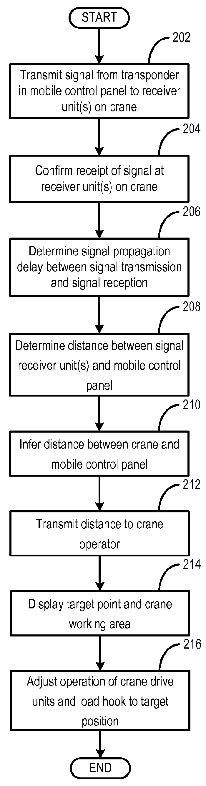
[0023]In addition to such a stationary control panel, crane 1 advantageously comprises a mobile control panel 7, for example in the form of a radio remote con...


PUM


Abstract

The present disclosure concerns a crane, in particular a tower crane, telescopic boom crane, harbour crane and the like, with a load hook that can be raised or lowered via movable crane elements, and moved within a crane working area by operating drive units associated with the crane elements. The crane is provided with a control unit with input means to control the drive units. According to the present disclosure, the crane uses a mobile portable target signal transmitter that can be variably positioned in the crane working area, and positioning means for automatically determining the current position of the target signal transmitter relative to the load hook and/or a crane element, and target control means for automatically controlling the drive units in response to a signal from the positioning means, such that the load hook is automatically moved to the mobile target signal transmitter.

Description

CROSS REFERENCE TO RELATED APPLICATIONS[0001]The present application is a continuation-in-part of PCT International Application PCT / EP2014 / 000732, entitled “Remote-Controlled Crane,” filed on Mar. 18, 2014, which claims priority to German Patent Application No. 10 2013 006 258.6, filed on Apr. 11, 2013, the entire contents of each of which are hereby incorporated by reference in their entirety for all purposes.TECHNICAL FIELD[0002]The present disclosure relates to a crane, in particular a tower crane, telescopic boom crane, harbour crane and the like, with a load hook that can be raised or lowered by means of movable crane elements, and moved within a crane working area by operating drive units associated with the crane elements. The crane is provided with a control unit with input means to control the drive units.BACKGROUND AND SUMMARY[0003]In cranes of the said type, the load hook can usually be raised and lowered by means of a hoisting cable that runs from a crane jib and an asso...

Claims


Application Information

Patent Timeline
IPC IPC(8): B66C13/40B66C13/46B66C23/16
CPCB66C13/40B66C13/46B66C23/16B66C13/44B66C13/48B66C2700/082B66C2700/088
Inventor FENKER, OLIVERHOFMANN, ROMAN
Owner LIEBHERR WERK BIBERACH
Why Eureka
Try Eureka