
Shunt flusher

Active Publication Date: 2016-02-11
CHILDRENS MEDICAL CENT CORP
View PDF7 Cites 27 Cited by
  • Summary
  • Abstract
  • Description
  • Claims
  • Application Information

AI Technical Summary

Benefits of technology

The invention is about using a small amount of flushing fluid to flush blockages in a device used to treat brain infections. The fluid is pressurized and then released quickly, creating forceful spikes that push away blockages. This process helps to keep the device clear and reduces the risk of the blockages coming back. The device also has backup pores to restart flow if the main pores become blocked. Overall, this technique allows for effective treatment with minimal fluid consumption.

Problems solved by technology

Shunt obstruction can occur at any time after insertion, and all points along the shunt course are suspect when assessing for shunt malfunction.
Removal in this circumstance is complicated by the risk of bleeding caused by avulsion of choroid plexus if the catheter is forcefully removed.
The inventors have found that the use of conventional back flushing arrangements have limitations and can be ineffective altogether due to the small amount of flushing liquid available in existing shunt systems.
Moreover, using these built-in mechanisms for flushing may make the situation even worse—a more severe clogging is expected due to rapid suction of CSF back into the catheter and / or chamber immediately after flushing is performed.

Method used


Image

  • Shunt flusher
  • Shunt flusher
  • Shunt flusher

Examples


Embodiment Construction

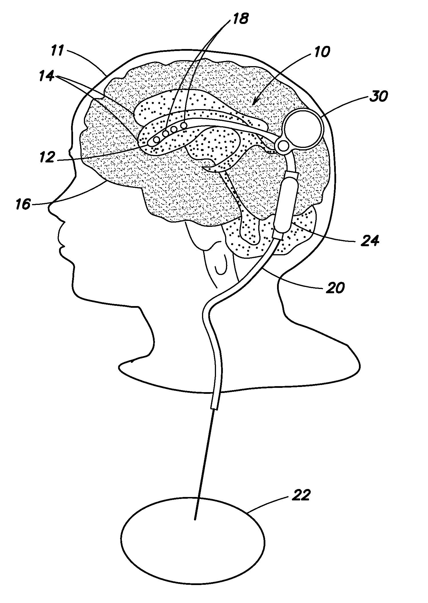
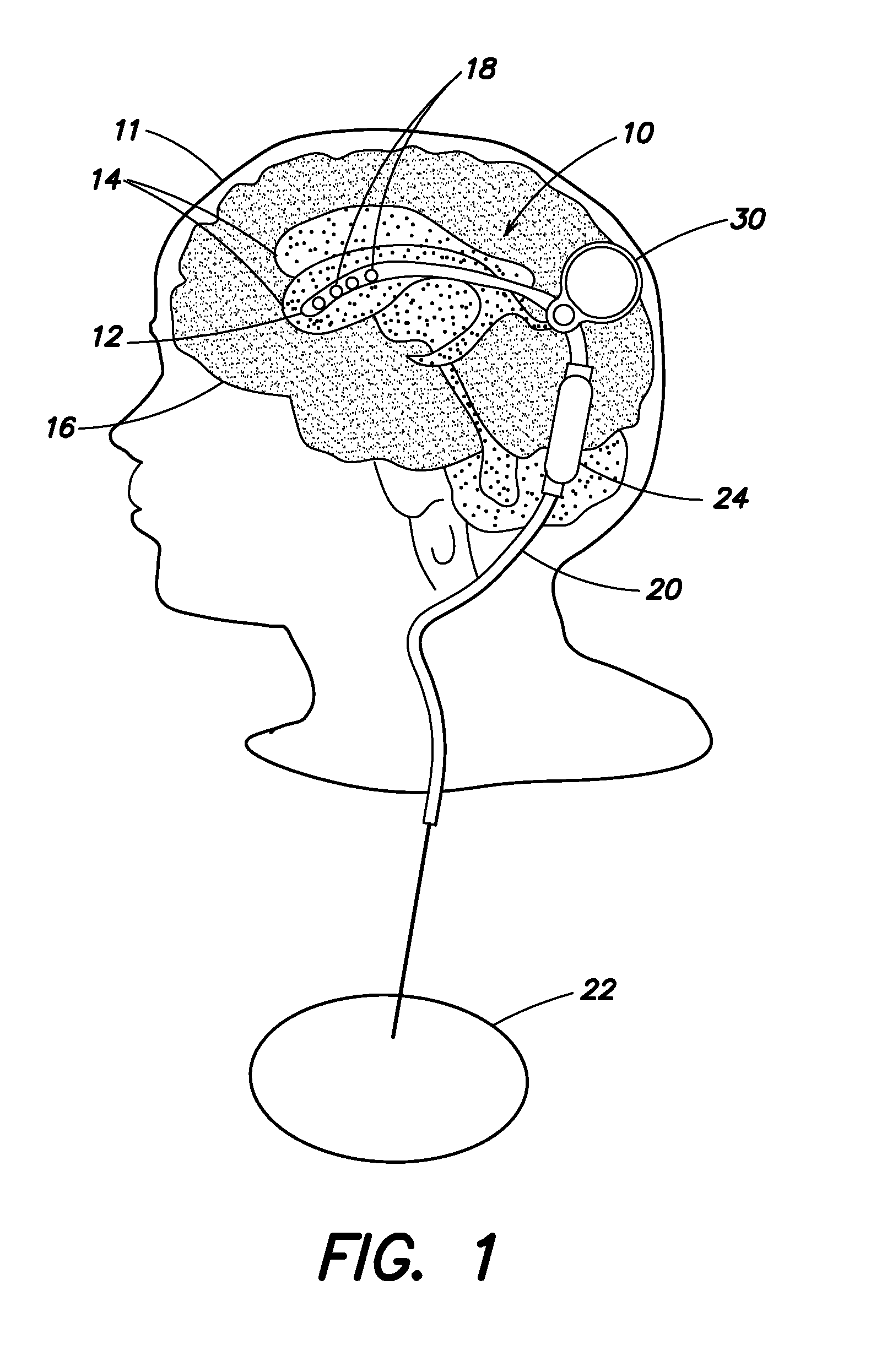
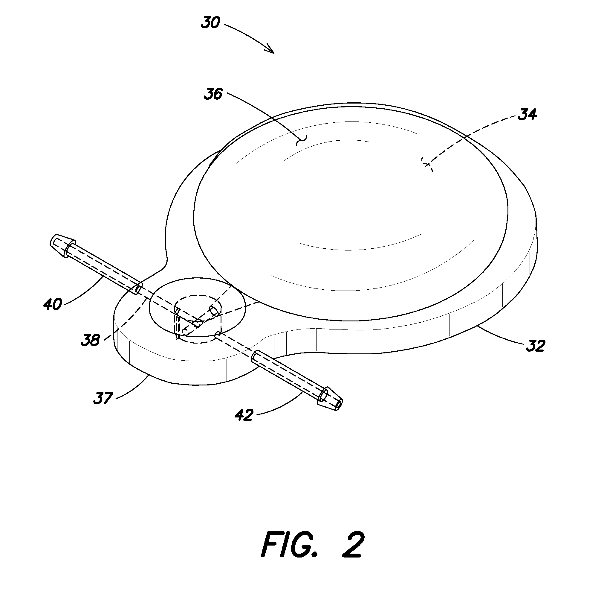
[0027]Aspects are directed to devices and systems used to flush obstructions in the ventricular catheter. The devices or systems are positioned between the catheter tip and the shunt valve and include a reservoir holding CSF. It should be appreciated that as used herein, “proximal” refers to the upstream portion of the shunt system, such as the catheter side of the shunt system. The proximal side generally extends from the ventricle to the shunt valve. “Distal” refers to the downstream portion of the shunt system, such as the drainage side of the shunt system. The distal side generally extends from the shunt valve to the peritoneum or other CSF resorbtion site. A conduit allows CSF to drain to the shunt valve and to fill the reservoir. In one embodiment, the device also includes a check valve disposed within a valve housing selectively movable between a normal flow position and a backflow position. When in the normal flow position, the check valve and housing allow free flow of CSF ...


PUM


Abstract

A device and system for flushing a shunt catheter utilizes the available cerebrospinal fluid (CSF) to flush a blocked catheter. The CSF is pressurized to a predetermined amount and then allowed to suddenly, rapidly and forcefully purge any occlusions. The rapid release of CSF produces flow jets from the catheter pores into the ventricle. This impulse, or “cough”, will push and divert choroid plexus and / or other blockages away from the pores. The device and system may then be allowed to refill at a slow rate, thus reducing the possibility of rapid suction of fluid back into the system and the attendant possibility of drawing the choroid plexus back into the pores. The catheter at the proximal end may also include back-up pores that can be opened to restart flow from the ventricle should the primary pores remain blocked after a flushing attempt.

Description

BACKGROUND[0001]1. Field[0002]Aspects herein relate to devices and systems cooperating with shunt systems to flush occlusions in or near shunt catheters and in particular to devices and systems cooperating with shunts used to treat hydrocephalus.[0003]2. Discussion of Related Art[0004]Hydrocephalus is a condition in which cerebrospinal fluid (CSF) is unable to drain through natural mechanisms and instead accumulates in the ventricles of the brain. Conventional treatment of hydrocephalus includes the use of a shunt catheter or other drain tube having a proximal end inserted into the ventricle(s) and the opposite, distal end of the tube emptying into the abdominal cavity. The proximal end of the catheter includes one or more pores through which the CSF can enter and flow to the abdominal cavity. A one-way check valve is often included in the line, typically closer to the proximal end of the shunt. The valve acts to maintain the proper pressure in the ventricles, yet allow drainage of ...

Claims


Application Information

Patent Timeline
IPC IPC(8): A61M27/00
CPCA61M2202/0464A61M27/006A61M2039/224A61M2210/0693A61M5/14276A61M2025/0019
Inventor MADSEN, JOSEPHANOR, TOMER
Owner CHILDRENS MEDICAL CENT CORP
Learn More