Robot System And Method For Calibration

a robot system and calibration technology, applied in the field of robot system and calibration method, can solve the problems of inability to know in advance or change the position of the calibration marker during work, and achieve the effect of fast and accurate calibration of the object identification unit and accurate calibration of the different end effectors

Active Publication Date: 2016-02-11
ABB (SCHWEIZ) AG
View PDF0 Cites 41 Cited by
  • Summary
  • Abstract
  • Description
  • Claims
  • Application Information

AI Technical Summary

Benefits of technology

[0017]With the method a fast and accurate calibration of an object identification unit to a robot unit is accomplished. The calibration can be done with a two dimensional calibration marker that can be permanently attached to the robot. There is no longer a need for time consuming teaching of a tool centre point, TCP, against a checkerboard which can take up to an hour to accomplish. The described calibration method can be done within some minutes and can be periodically executed without having to re-attach a calibration marker to the robot. The position of the calibration marker does not have to be known in advance. The calibration can thus be accurately done for different end effectors even if the calibration marker has a different placement on the end effectors. Also, if the end effector includes soft parts such as padding, the placement of the calibration marker may become changed during work or cannot be known in advance. However, as the placement of the calibration marker does not need to be known in advance, this will not be a problem.

Problems solved by technology

Also, if the end effector includes soft parts such as padding, the placement of the calibration marker may become changed during work or cannot be known in advance.

Method used


Image

  • Robot System And Method For Calibration
  • Robot System And Method For Calibration
  • Robot System And Method For Calibration

Examples


Embodiment Construction

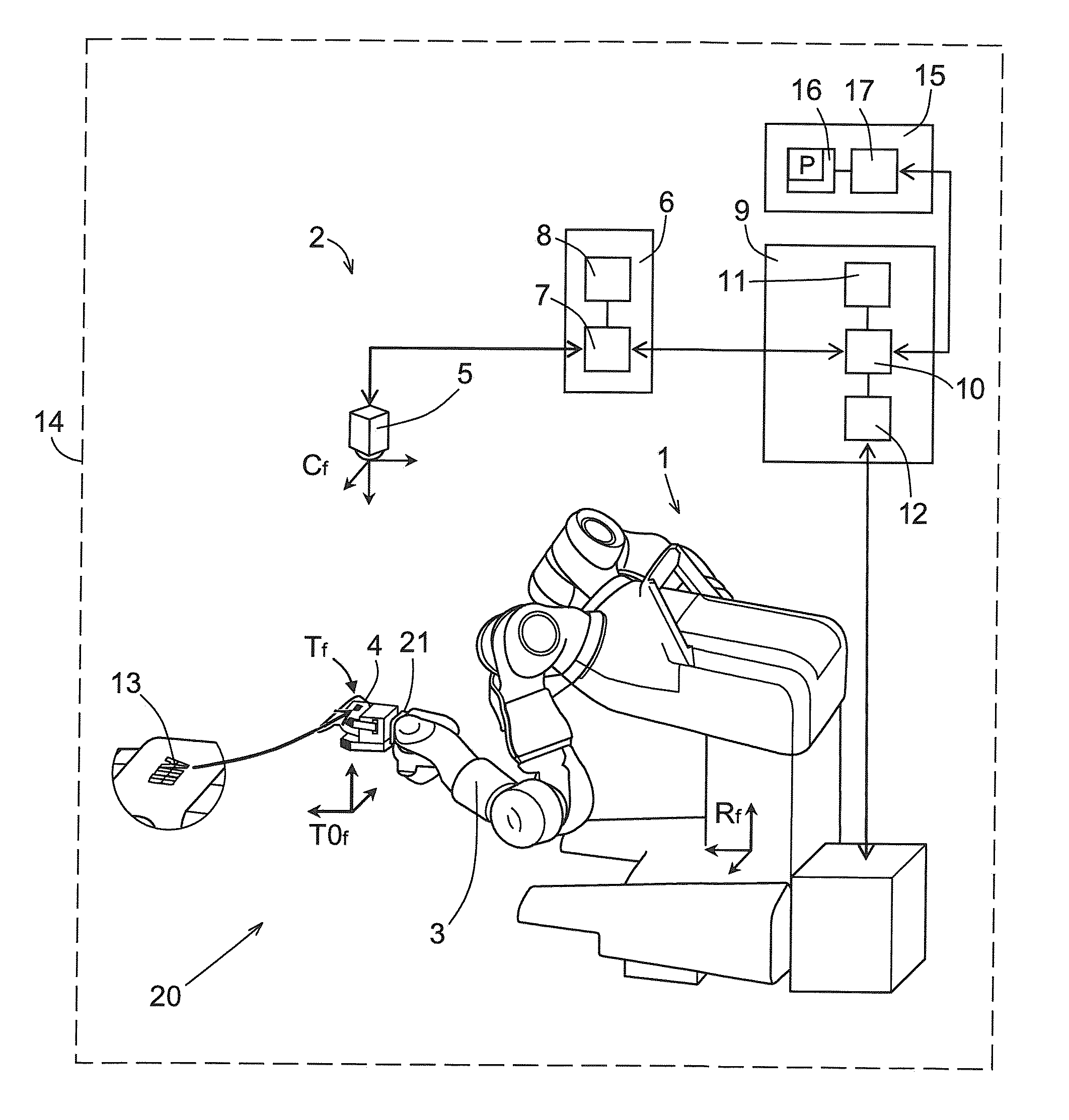
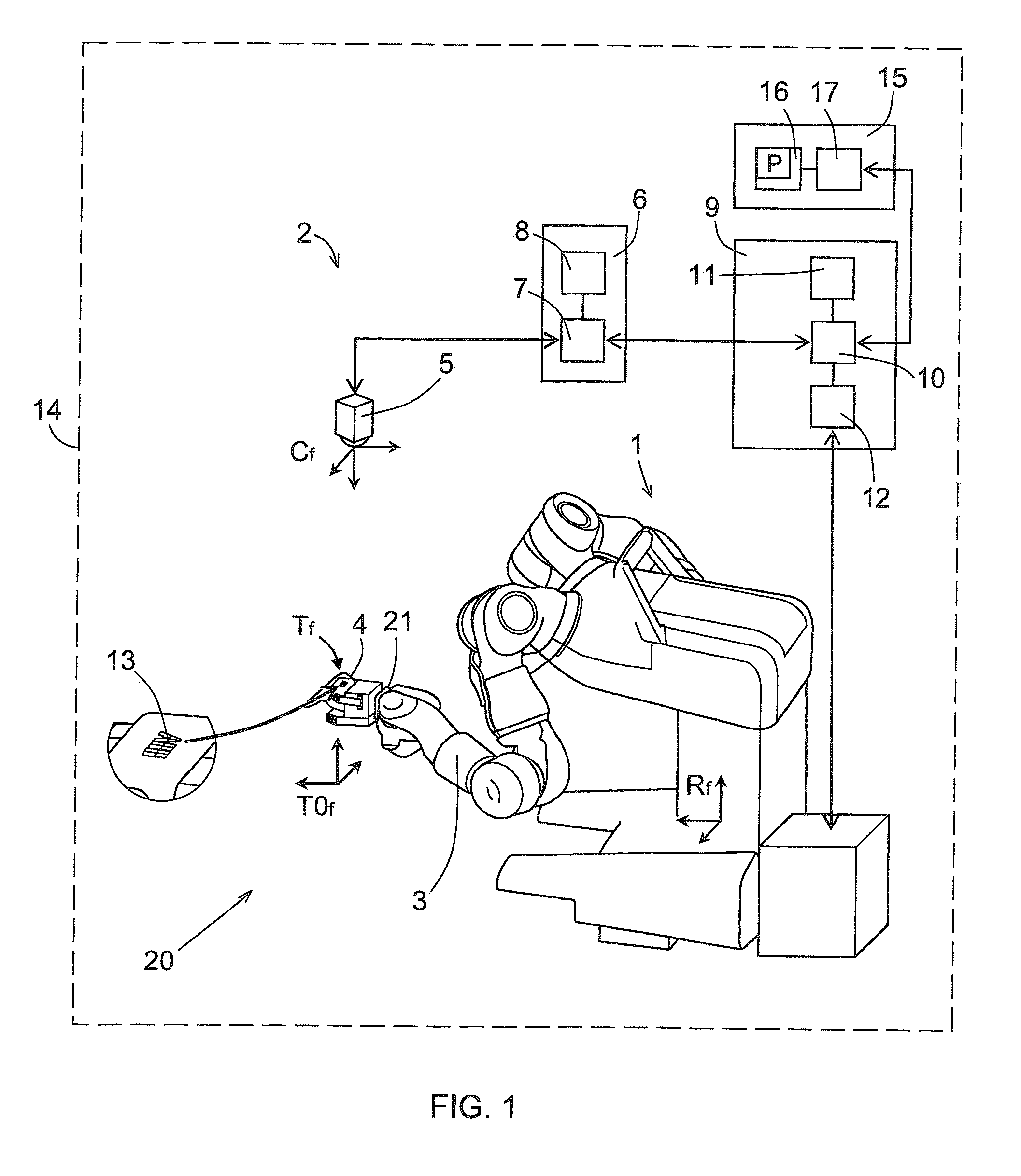
[0043]FIG. 1 illustrates an example of a robot system 14 comprising a robot unit 1 defining a first coordinate system Rf and an object identification unit 2 defining a second coordinate system Cf. The robot unit 1 comprises a robot arm 3 with an end effector 4. The robot unit 1 is an articulated robot unit 1 and has six degrees of freedom. The robot arm 3 is also provided with a tool flange 21 defining a third coordinate system T0f. The end effector 4 is attached to the tool flange 21. The relationship between the first and third coordinate systems Rf and T0f is a known relationship.

[0044]The robot unit 1 and the object identification unit 2 are located at a work station 20. The robot unit 1 is configured to perform work at the work station 20.

[0045]The robot unit 1 comprises a robot controller 9 configured to control movement of the robot arm 3 by means of controlling a plurality of electric motors on the robot arm 3. The robot controller 9 comprises a programming unit 10, e.g. a c...


PUM


Abstract

A method and a system for calibrating a first coordinate system Rf of a robot unit with a second coordinate system Cf of an object identification unit, wherein the robot unit includes a robot arm with an end effector and the object identification unit includes a camera unit. The calibration is performed using a calibration marker on the end effector. The method determines the intrinsic and the extrinsic parameters of the camera unit in two steps, a first step where the intrinsic parameters and a rotational part of the extrinsic parameters are determined, and a second step where a translational part of the extrinsic parameters are determined.

Description

FIELD OF THE INVENTION[0001]The present invention relates to techniques for calibration of a coordinate system of an object identification unit to a coordinate system of a robot unit.BACKGROUND OF THE INVENTION[0002]A camera can be used to aid a robot in different tasks such as finding and grasping objects. The camera then acts as a visual sensor to the robot. However, to be able to coordinate what the camera senses with actions of the robot, the relationship between the coordinate system of the camera and the coordinate system of the robot has to be known. This can be done by calibrating the camera to a coordinate system common with a coordinate system of the robot.[0003]The calibration problem can be seen as determining the intrinsic and the extrinsic parameters of the camera. The intrinsic parameters define the focal length and the aspect ratio of the camera, i.e. the ratio between the width and the height of the imaging elements in the camera, and skew. The extrinsic parameters ...

Claims


Application Information

Patent Timeline
Patent Type & Authority Applications(United States)
IPC IPC(8): B25J9/16
CPCB25J9/1692Y10S901/09B25J9/1697B25J9/1607G05B2219/39008
Inventor LUNDBERG, IVAN
Owner ABB (SCHWEIZ) AG
Why Eureka
Try Eureka