Silent chain and silent chain transmission device

a transmission device and silent chain technology, applied in the direction of driving chains, chain elements, belts/chains/gearings, etc., can solve the problems of weakening of the silent chain, so as to improve the silent chain around the sprocket, suppress periodic noise and vibration, and reduce string vibration and meshing noise

Active Publication Date: 2016-02-11
TSUBAKIMOTO CHAIN CO
View PDF30 Cites 2 Cited by
  • Summary
  • Abstract
  • Description
  • Claims
  • Application Information

AI Technical Summary

Benefits of technology

[0013]Furthermore, in a high load region where the silent chain is wound while being subject to tension from the sprocket, a force is applied in a direction in which the pitch between rolling points decreases due to strong elasticity and generates a force in a direction in which the silent chain detaches from the teeth of the sprocket. This makes it easier for link teeth of the inner plate to run on the sprocket teeth and creates a risk of so-called tooth skipping.
[0037]With the configuration according to present claim 8, due to the pitch between rolling points being different between the guide row and the non-guide row, a timing and a position of contact with the sprocket changes between the middle plate and the inner plates. As a result, periodic noise and vibration are suppressed and, furthermore, a string vibration sound and a meshing noise can be reduced.

Problems solved by technology

However, when a pitch relationship is set as described above, since the pitch between rolling points in at least the non-guide row becomes shorter than the sprocket pitch in the silent chain that is wound around the sprocket in an initial state and a low load state where wear elongation has not occurred, winding around the sprocket loosens.
As a result, a problem occurs where, due to unstable chain behavior, a string vibration sound of the silent chain becomes louder and a meshing noise between the silent chain and the sprockets worsens.
In such regions, since the pitch between rolling points in at least the non-guide row becomes shorter than the sprocket pitch and, similarly, winding of the silent chain around the sprocket loosens and chain behavior is not stable, there is a problem that a string vibration sound of the silent chain becomes louder and a meshing noise between the silent chain and the sprockets worsens.
This makes it easier for link teeth of the inner plate to run on the sprocket teeth and creates a risk of so-called tooth skipping.

Method used


Image

  • Silent chain and silent chain transmission device
  • Silent chain and silent chain transmission device
  • Silent chain and silent chain transmission device

Examples


first embodiment

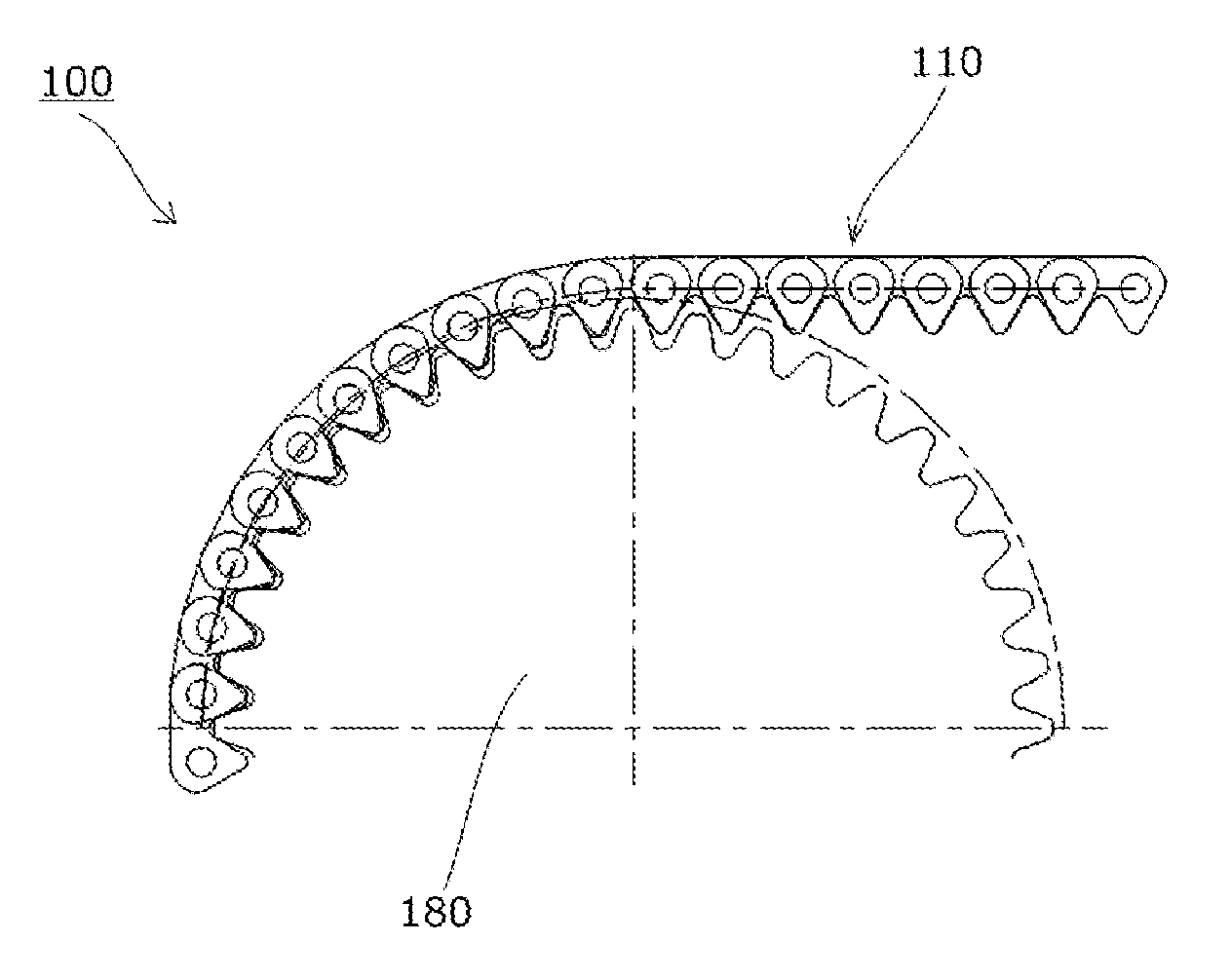
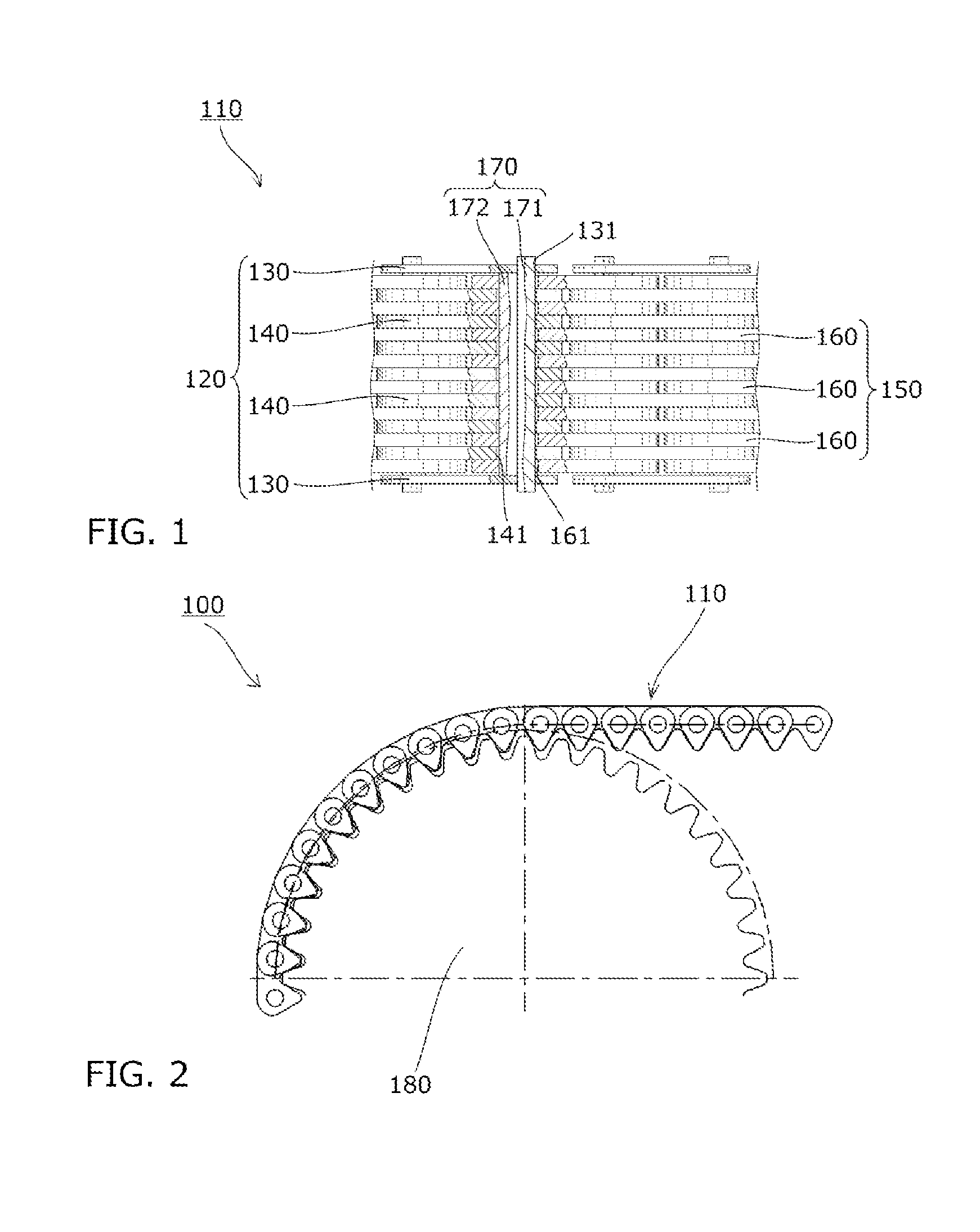
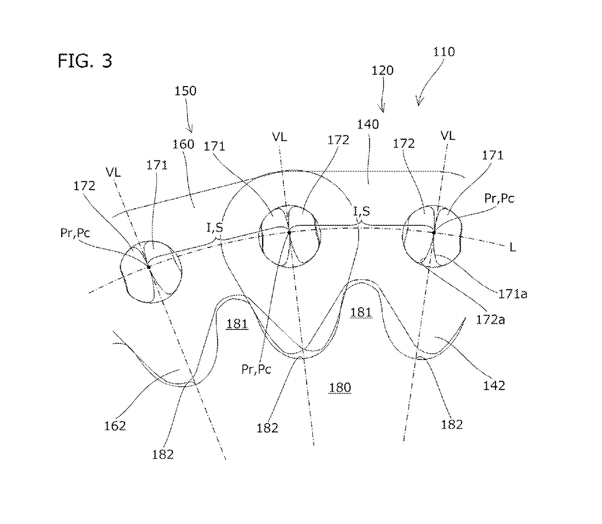
[0049]As shown in FIG. 1, in a silent chain 110 according to a first embodiment of the present invention, a plurality of guide rows 120 and a plurality of non-guide rows 150 are alternately arranged in a chain longitudinal direction while being staggered by half a pitch, and bendably connected by a pair of locker pins 170. As partially shown in FIG. 2, the silent chain 110 is wound around a sprocket 180 to constitute a silent chain transmission device 100 according to the first embodiment of the present invention.

[0050]The guide rows 120 of the silent chain 110 are made up of a pair of left and right guide plates 130 that are arranged on both outer sides in a chain width direction and a plurality of middle plates 140 that are arranged between the pair of left and right guide plates 130. In addition, the non-guide rows 150 are made up of a plurality of inner plates 160 that are arranged parallel to each other in the chain width direction.

[0051]The pair of locker pins 170 is made up o...

second embodiment

[0074]As shown in FIG. 6, in a silent chain according to a second embodiment of the present invention, a diameter of pin holes 241 and 261 of a middle plate and inner plates in the chain longitudinal direction are set larger than a diameter of the pin holes 241 and 261 thereof in a chain height direction, and sectional shapes of a long pin 271 and a short pin 272 are set thicker in the chain longitudinal direction.

[0075]In addition, in a similar manner to the first embodiment, in a state where the pair of locker pins 271 and 272 are in contact with each other on rolling surfaces 271a and 272a, the pin hole 261 of the inner plate 260 has a size that causes a gap to be created between a seat surface 263 of the inner plate 260 and the back surface of the short pin 272, and the pin hole 241 of the middle plate 240 has a size that causes a gap to be created between a seat surface 243 of the middle plate 240 and the back surface of the long pin 271.

[0076]In other words, as shown in FIG. 6...


PUM


Abstract

An object of the present invention is to provide a silent chain and a silent chain transmission device which stabilize chain behavior during chain travel to suppress an occurrence of tooth skipping and to reduce a string vibration sound and a meshing noise with simple configurations. In a silent chain 110, a pin hole 161 of an inner plate 160 and a pair of locker pins 170 are configured in such a size that a gap is formed between a seat surface 163 and a back surface of a short pin 172 in a state where the pair of locker pins 170 are in contact with each other on rolling surfaces 171a and 172a.

Description

BACKGROUND OF THE INVENTION [0001]1. Field of the Invention[0002]The present invention relates to a silent chain and a silent chain transmission device made up of the silent chain and a sprocket.[0003]2. Description of the Related Art[0004]Conventionally, a silent chain is known in which a guide row made up of a pair of left and right guide plates and a middle plate disposed between the pair of left and right guide plates and a non-guide row made up of a plurality of inner plates are alternately connected in a chain longitudinal direction by a pair of locker pins made up of a long pin and a short pin to be inserted into a pair of front and rear pin holes provided on the middle plate and the inner plates (for example, refer to Japanese Patent Application Laid-open No. 2002-130384).[0005]In addition, a silent chain transmission device is known which is capable of transmitting power among a plurality of sprockets by winding a silent chain around the plurality of sprockets.[0006]General...

Claims


Application Information

Patent Timeline
Patent Type & Authority Applications(United States)
IPC IPC(8): F16G15/02F16G13/04
CPCF16G15/02F16G13/04F16G13/08
Inventor SATO, TOSHIFUMISASAKI, TAKEOHAMAGUCHI, SHUJI
Owner TSUBAKIMOTO CHAIN CO
Why Eureka
Try Eureka