

Pixel array and head up display
a display panel and array technology, applied in the field of pixel arrays and displays, can solve the problems of insufficient light energy conversion efficiency of conventional lcds, and achieve the effect of enhancing the transmittance of the display panel without compromising the image quality of the display panel
- Summary
- Abstract
- Description
- Claims
- Application Information
AI Technical Summary
Benefits of technology
Problems solved by technology
Method used
Image

Examples
first embodiment
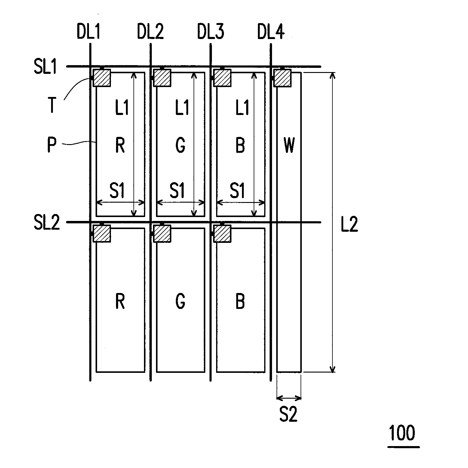
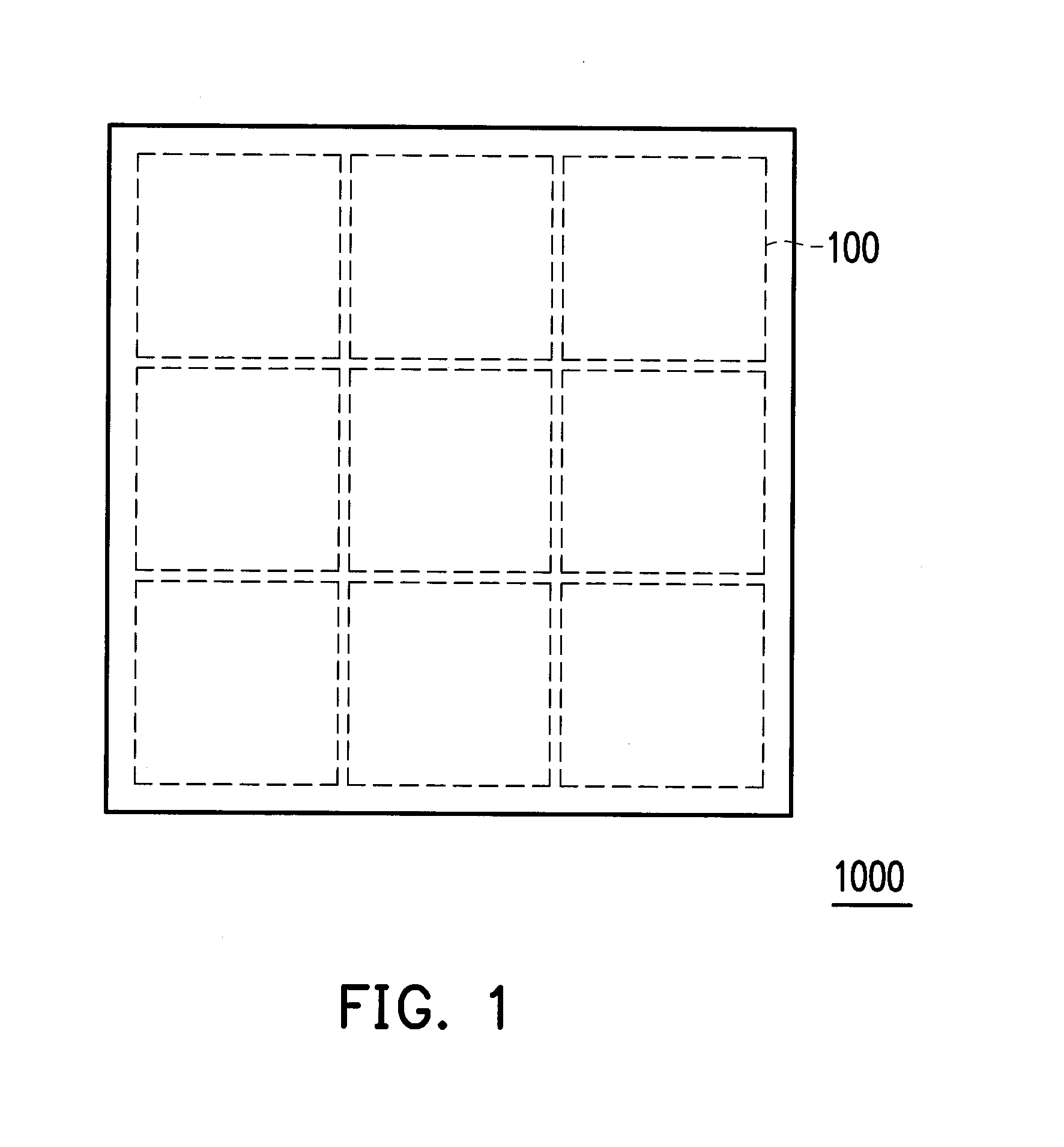
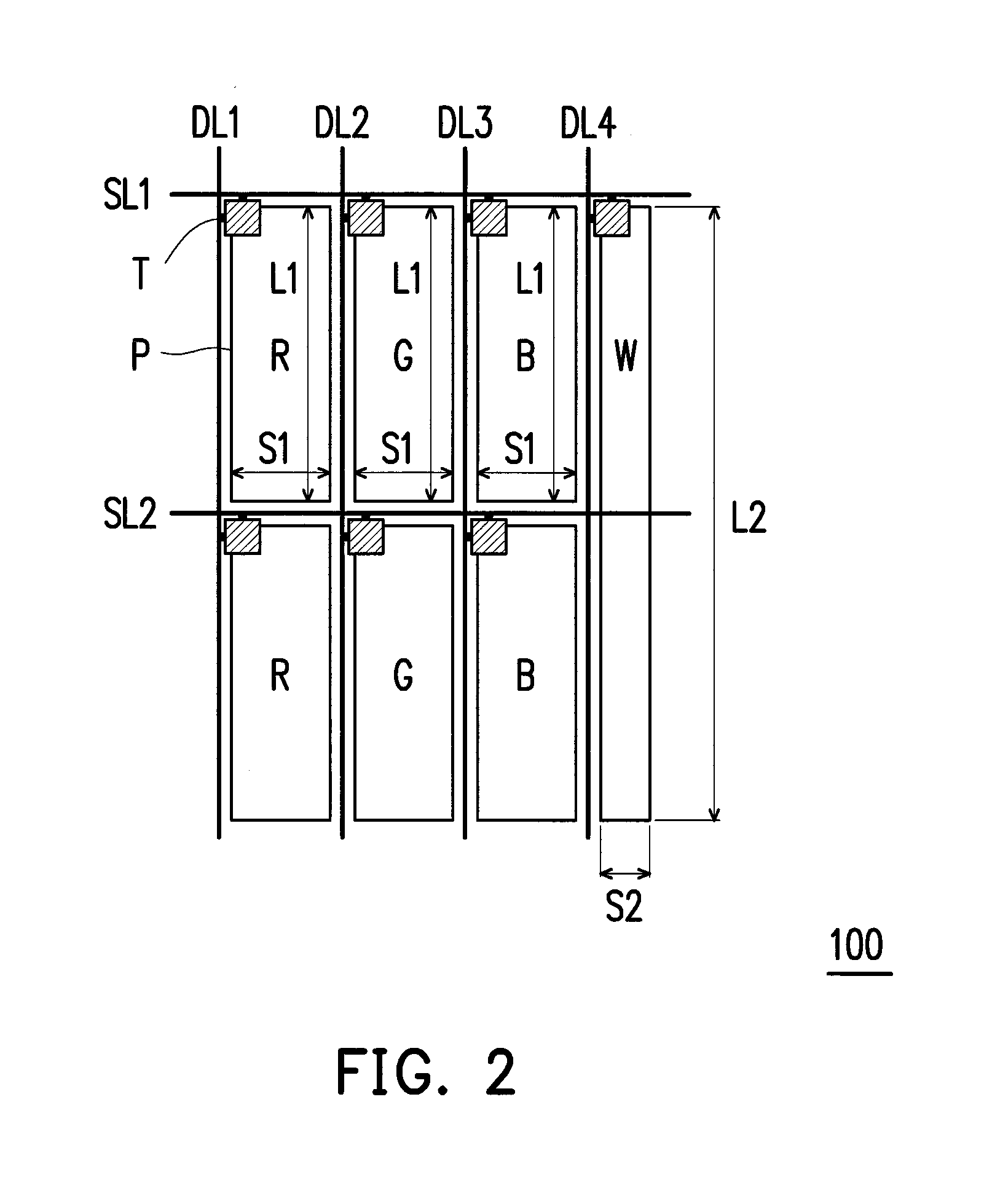
[0036]FIG. 1 is a schematic top view illustrating a pixel array according to an embodiment of the invention. The pixel array 1000 may include a plurality of repeat unit sets 100. The repeat unit sets 100 may be arranged in an array, as shown in FIG. 1. In the present embodiment, identical unit sets are repeatedly arranged in an array, and each of the identical unit sets is named the repeat unit set. FIG. 2 is a schematic top view illustrating a repeat unit set according to the invention. With reference to FIG. 1 and FIG. 2, the repeat unit set 100 provided in the present embodiment includes a first scan line SL1, a second scan line SL2, a first data line DL1, a second data line DL2, a third data line DL3, a fourth data line DL4, and seven sub-pixels. The seven sub-pixels are two first color sub-pixels R, two second color sub-pixels G, two third color sub-pixels B, and a fourth color sub-pixel W. According to the present embodiment, the first color sub-pixels R are red sub-pixels, th...
second embodiment
[0050]FIG. 6 is a schematic top view illustrating a repeat unit set according to the invention. With reference to FIG. 2 and FIG. 6, the repeat unit set 200 shown in FIG. 6 is similar to the repeat unit set 100 shown in FIG. 2; therefore, the identical or similar components in these embodiments are represented by the identical or similar reference numbers and will not be further explained. The difference between the repeat unit sets 200 and 100 lies in that each repeat unit 200 is constituted by thirteen sub-pixels. The thirteen sub-pixels are four first color sub-pixels R, four second color sub-pixels G, four third color sub-pixels B, and one fourth color sub-pixel W. According to the present embodiment, the first color sub-pixels R are red sub-pixels, the second color sub-pixels G are green sub-pixels, the third color sub-pixels B are blue sub-pixels, and the fourth color sub-pixel W is a white sub-pixel; however, the invention is not limited thereto.
[0051]With reference to FIG. 6...
third embodiment
[0062]FIG. 13 is a schematic top view illustrating a repeat unit set according to the invention. With reference to FIG. 6 and FIG. 13, the repeat unit set 300 shown in FIG. 13 is similar to the repeat unit set 200 shown in FIG. 6; therefore, the identical or similar components in these embodiments are represented by the identical or similar reference numbers and will not be further explained. Each of the repeat unit sets 300 and 200 are constituted by thirteen sub-pixels consisting of four first color sub-pixels R, four second color sub-pixels G, four third color sub-pixels B, and one fourth color sub-pixel W, and the relative arrangement of the sub-pixels in the repeat unit set 300 is the same as that in the repeat unit set 200. According to the present embodiment, the first color sub-pixels R are red sub-pixels, the second color sub-pixels G are green sub-pixels, the third color sub-pixels B are blue sub-pixels, and the fourth color sub-pixel W is a white sub-pixel; however, the i...
PUM
| Property | Measurement | Unit |
|---|---|---|
| size | aaaaa | aaaaa |
| size | aaaaa | aaaaa |
| size | aaaaa | aaaaa |
Abstract
Description
Claims
Application Information