
Interface circuit and packet transmission method thereof

a technology of interface circuit and packet transmission method, which is applied in the field of interface circuit techniques, can solve the problems of increasing the overhead caused by headers included in each packet, and achieve the effect of improving the overhead

Active Publication Date: 2016-02-11
SAMSUNG ELECTRONICS CO LTD
View PDF4 Cites 17 Cited by
  • Summary
  • Abstract
  • Description
  • Claims
  • Application Information

AI Technical Summary

Benefits of technology

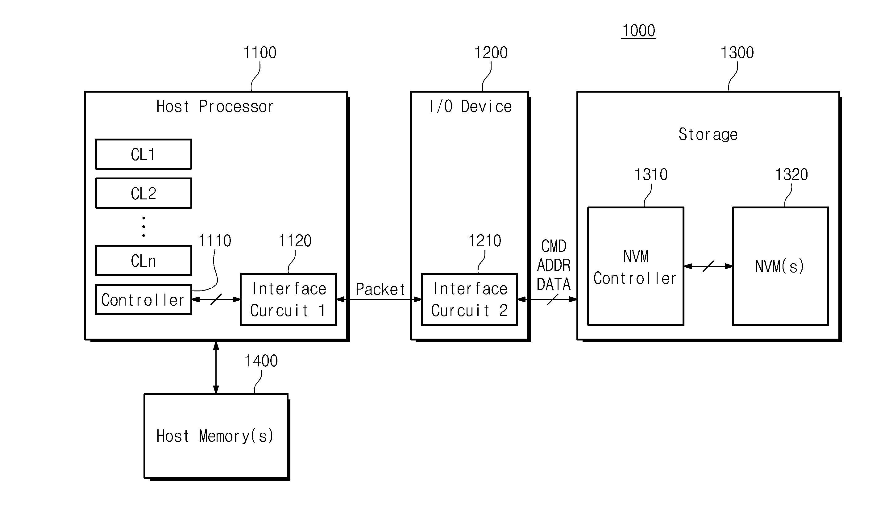
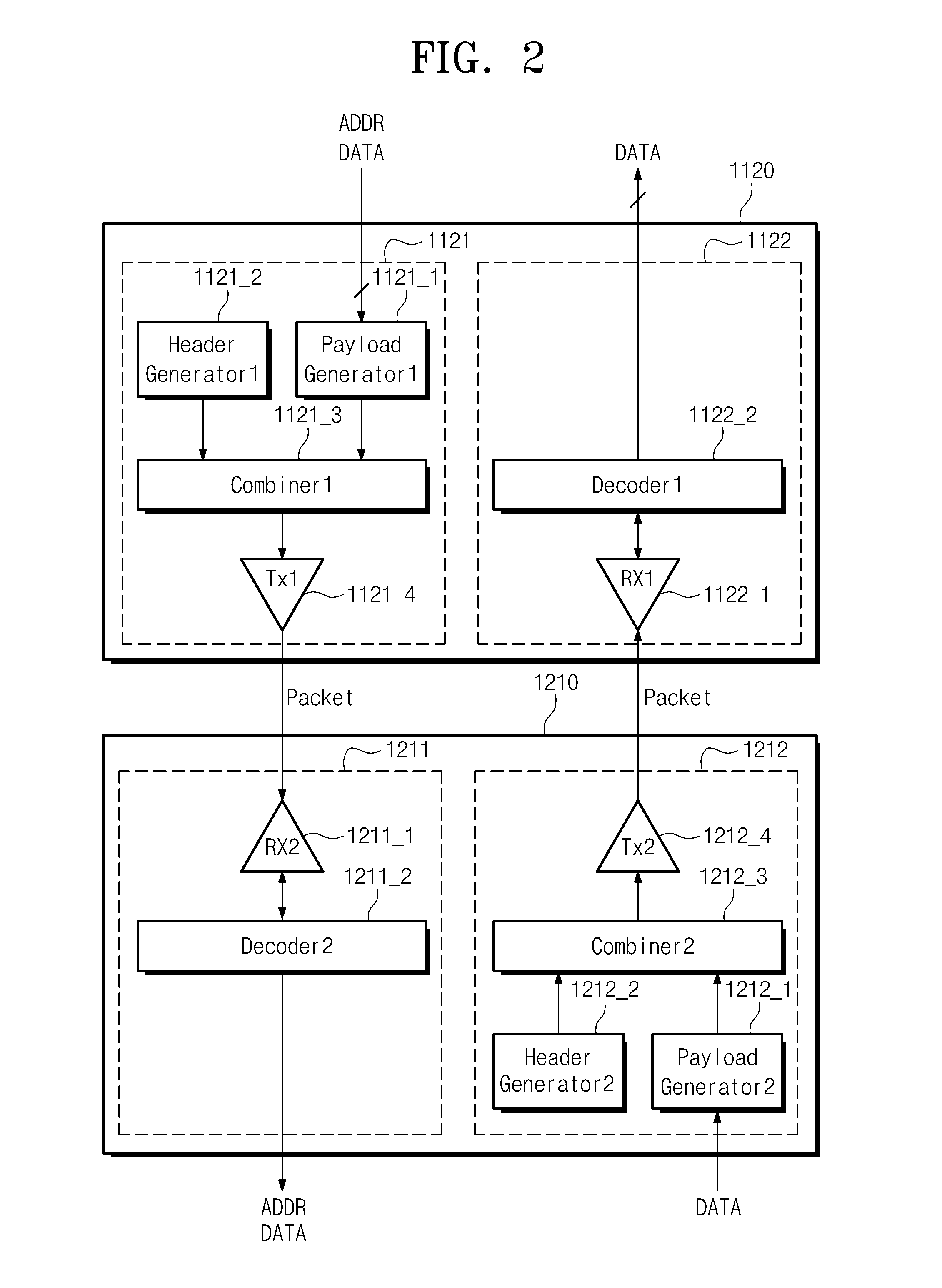
The patent text describes an interface circuit and a packet transmission method that can efficiently transmit data packets. The interface circuit includes a transmission unit that packages data into a payload, adds a header with information about the data, and generates a transaction layer packet. The method involves combining the header, payload, and CRC area to generate the transaction layer packet. The interface circuit can also receive and decode multiple packets, and output the data stored in cache lines of a host processor. The technical effects of this invention include improved data transmission speed and reliability, as well as efficient use of network bandwidth.

Problems solved by technology

Therefore, as the number of packets used to transmit data having a small size increases, the amount of overhead caused by a header included in each of the packets may also increase.

Method used


Image

  • Interface circuit and packet transmission method thereof
  • Interface circuit and packet transmission method thereof
  • Interface circuit and packet transmission method thereof

Examples


Embodiment Construction

[0049]Some example embodiments in accordance with the inventive concepts will now be described more fully hereinafter with reference to the accompanying drawings.

[0050]Example embodiments will now be described more fully with reference to the accompanying drawings, in which some example embodiments are shown. In the drawings, the thicknesses of layers and regions are exaggerated for clarity. Like reference numerals in the drawings denote like elements.

[0051]Detailed illustrative example embodiments are disclosed herein. However, specific structural and functional details disclosed herein are merely representative for purposes of describing example embodiments. Example embodiments may be embodied in many alternate forms and should not be construed as limited to only those set forth herein.

[0052]It should be understood, however, that there is no intent to limit this disclosure to the particular example embodiments disclosed. On the contrary, example embodiments are to cover all modifi...


PUM


Abstract

A packet transmission method includes packaging a plurality of data in the form of a payload; storing information on whether the plurality of data are packaged in a header, the payload or a CRC area including a transmission error check code of the plurality of data; combining the header, the payload, and the CRC area with each other to generate a transaction layer packet; and outputting a packet including the transaction layer packet.

Description

CROSS-REFERENCE TO RELATED APPLICATIONS[0001]This US non-provisional patent application claims priority under 35 USC §119 to Korean Patent Application No. 10-2014-0102427, filed on Aug. 8, 2014, the disclosure of which is incorporated by reference in its entirety herein.BACKGROUND[0002]1. Technical Field[0003]Example embodiments relate to interface circuit techniques. For example, at least some example embodiments relate to an interface circuit to generate and transmit multi-data according to communication protocols.[0004]2. Discussion of Related Art[0005]An interface circuit may transmit data within a computer system or between different computer systems by using various manners. Some computer systems may transmit data through an interface circuit in units of packets. An interface circuit may transmit data according to communication protocols. The interface circuit may operate according to protocols such as Fiber Channel (FC), Universal Serial Bus (USB) 3.0, Serial Attached SCSI (S...

Claims


Application Information

Patent Timeline
Patent Type & Authority Applications(United States)
IPC IPC(8): G06F13/40G06F12/08G06F13/42
CPCG06F13/4027G06F2212/222G06F12/0842G06F13/4282G06F12/0866
Inventor LEE, EUNJIWOO, JUNGHYO
Owner SAMSUNG ELECTRONICS CO LTD
Learn More