Protective Case for Portable Electronic Device with Integrated Dispensable and Retractable Charge and Sync Cable

a portable electronic device and charging cable technology, applied in the direction of electrical apparatus casings/cabinets/drawers, coupling device connections, transportation and packaging, etc., can solve the problems of not providing an integrated charge/sync cable, putting a strain on battery capacity and uninterrupted device use, etc., to achieve quick and easy retraction or recoil

Active Publication Date: 2016-02-11
CORDCASE LLC
View PDF1 Cites 22 Cited by
  • Summary
  • Abstract
  • Description
  • Claims
  • Application Information

AI Technical Summary

Benefits of technology

[0008]The present invention allows the user to dispense the USB Type A charge / sync connector by pulling at only one end, with more than 3 ft. of charge cable being potentially pulled from the case assembly. This allows the user to fully use the features and capabilities of the electronic device while the device is charging or syncing. Once charging or syncing is complete, the present invention allows the user to quickly and easily retract or recoil the USB Type A connector and attached cable by spinning / winding the spool assembly using a finger pressed into one of the circular conical depressions on the spool top surface, or by use of a recoil spring, the cable can be automatically rewound onto the spool assembly. The present invention by means of the PCBs and electrical contacts allows the user to charge / sync the portable electronic device in any dispensed / extracted length position of USB Type A connector. The present invention can be manufactured using industry standard tooling and techniques, no special assembly tooling is required. The present invention also is manufactured using industry standard OEM cable assemblies so as to be compatible with all current and future OEM portable electronic devices such as the ever evolving designs of cell phones.

Problems solved by technology

Today's increased use of video streaming and GPS navigation on the latest smartphones have put a strain on battery capacity and uninterrupted device use.
While the patent covers the retraction of the spool back into the housing / case, the OEM end of the cable is not always connected / mated to the device, and the cable must be fully removed from the spool and manually connected to the portable electronic device before charging / sync.
U.S. Pat. No. 8,579,172 Monaco et al., provides several utilities in its case design such as drop protection, a belt clip, bottle opener, and earphone storage and dispensing, however it does not provide an integrated charge / sync cable.
While U.S. Pat. No. 7,297,001 Wu, and U.S. Pat. No. 7,255,595 Lo, is a transmission line wire winding device which is pulled at one end, it is not integrated into a protective portable electronic device case, nor does its fixed end constantly remain mated to the portable electronic device during the storage and use cycle.
It also requires the device / portable hard drive to be permanently mounted to the case assembly and does not allow easy case assembly removal for device maintenance or device “docking”.

Method used


Image

  • Protective Case for Portable Electronic Device with Integrated Dispensable and Retractable Charge and Sync Cable
  • Protective Case for Portable Electronic Device with Integrated Dispensable and Retractable Charge and Sync Cable
  • Protective Case for Portable Electronic Device with Integrated Dispensable and Retractable Charge and Sync Cable

Examples


Embodiment Construction

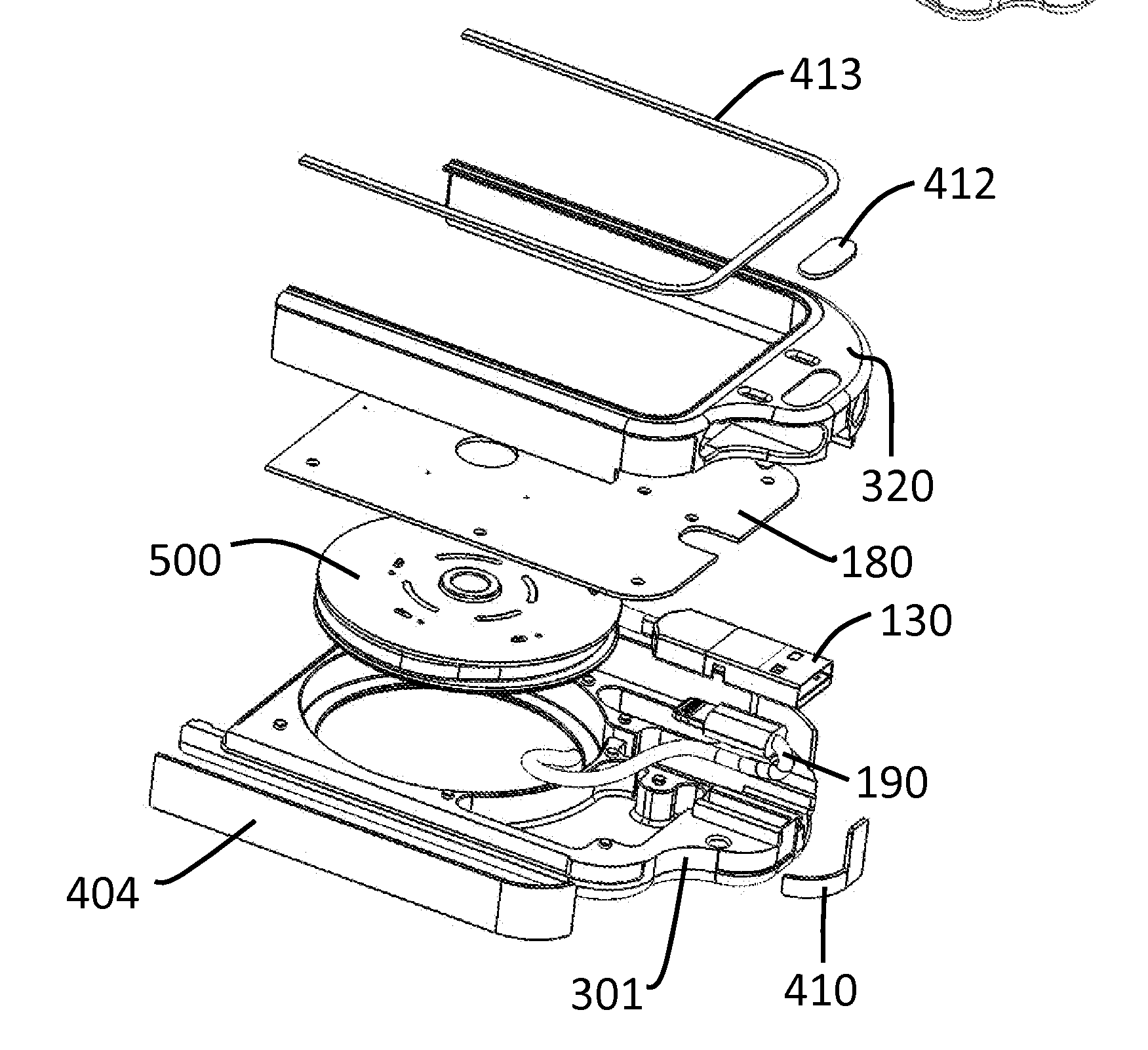
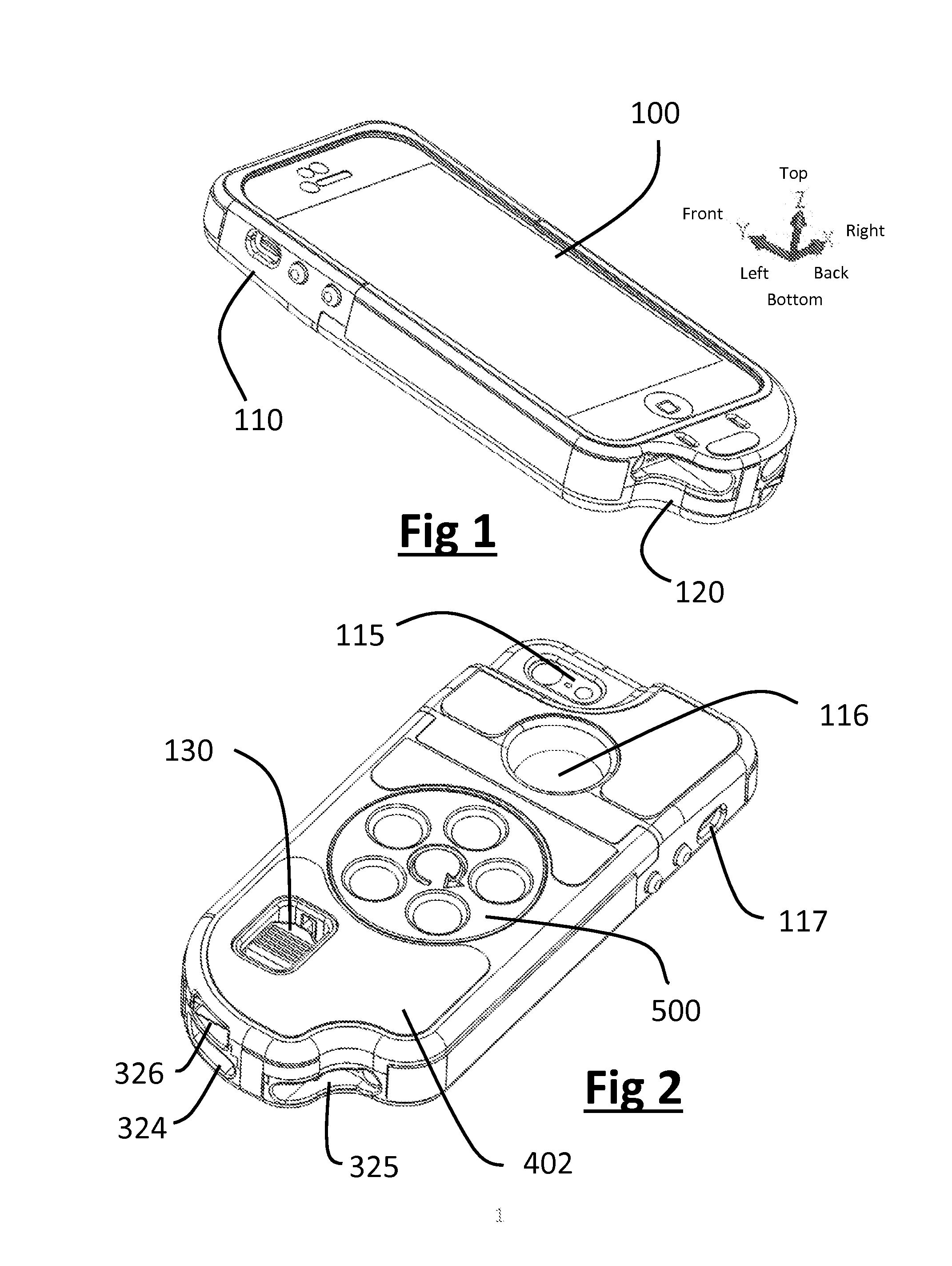
[0027]FIG. 1. Is a top left ISO view of the 2 protective case housing halves, nosecone housing assembly 110 and lower housing assembly 120 fully mated and assembled for use with a known portable electronic device 100. The coordinate system shown in FIG. 1., identifies the directions and axis referenced in this embodiment.

[0028]FIG. 2. Is a back left ISO view of the 2 protective case housing halves, nosecone housing assembly 110 and lower housing assembly 120 fully mated and assembled for use with a known portable electronic device 100. As can be seen in FIG. 2, the protective case allows for the full and uninhibited use of the device functionality through the nosecone housing assembly viewport 115 and nosecone housing assembly mute pocket 117 and lower housing assembly speaker / microphone Port A 324 and lower housing assembly speaker / microphone Port B 325. The present invention applies to all forms and manufacturers of portable electronic devices, and therefore different variations m...


PUM


Abstract

A protective case for a portable electronic device which incorporates a spool assembly containing a user dispensable and retractable Industry standard or OEM charge/sync cable. The case provides the user with the utility of always having a charge/sync cable available when needed while being discreetly housed in a low-profile ergonomically pleasing package. The case and spool assembly provide the user with up to 3 Ft or more of cable available for dispensing from the case while allowing the portable electronic device to be charged/synced at any desired dispensed length of cable, and can be manufactured using any thermoplastic, metal, wood, or composite. The dispensed cable and connector can be rewound onto the spool manually using the spool finger pockets. The 2 distinct case housing assemblies encase the device in a constraining pocket, utilizing ramped boss and pocket latching features to retain the case housing halves and the portable electronic device in the assembled and protected condition, while allowing the unobstructed use of the device's full functionality. The housing latching bosses and pockets are designed to provide adequate assembly integrity, while allowing for the easy removal of the lower housing assembly to provide “docking” access of the device to 3rd party accessories. The protective case utilizes several adhesive backed elastomeric decals mounted in complimentary shallow housing pockets, to provide drop and bump protection of the electronic device as well as anti-slip properties and aesthetic beautification.

Description

BACKGROUND OF THE INVENTION[0001]Today's society has adopted technology on a broad scale. This includes the adoption of personal hand held electronics for use in playing music, playing games, making phone calls, navigating the internet, tracking your exact location, checking the weather, etc. These electronic devices have taken the form of iPods®, iPhones®, iPads®, OEM Cell Phones, Personal Data Assistants (PDA's), handheld GPS navigation devices, portable music players, and the like. All of these handheld portable devices are battery powered and require charging With an external charge / sync cable specific to the OEMs charging and interconnect requirements. Today's increased use of video streaming and GPS navigation on the latest smartphones have put a strain on battery capacity and uninterrupted device use. This battery demand has required the device user to charge their devices more frequently. However, to be able to charge the device, the user must possess the charge / sync cable. ...

Claims


Application Information

Patent Timeline
Patent Type & Authority Applications(United States)
IPC IPC(8): H01R13/72H01R13/52H01R13/66H02J7/00H04B1/40
CPCH01R13/72H02J7/0042H04B1/40H01R13/52H01R13/665H04M1/15H04M1/185H04B1/3888H02G11/02H04R1/1033H01R35/025H04M1/0249H05K5/0247
Inventor GEORGE, JOSEPH J.SHEPARD, RYAN F.
Owner CORDCASE LLC
Why Eureka
Try Eureka