Magnetic Cable Fastener

a magnetic cable and fastener technology, applied in the field of magnetic cable fasteners, can solve the problems of cable falling or sag, cumbersome and difficult installation, and cannot be installed without screw drivers or wrenches,

Inactive Publication Date: 2016-02-18
TERMAX CORP
View PDF82 Cites 37 Cited by
  • Summary
  • Abstract
  • Description
  • Claims
  • Application Information

AI Technical Summary

Problems solved by technology

At least some of the fasteners require extended height or blind insertion and installation of the fasteners because the installer is not able to view the fastener or the mounting point on the body panel.
These known fasteners require fastening with a screw driver or wrench and thus are cumbersome and difficult to install especially in inaccessible areas.
Nor can they be installed without a screw driver or wrench for example on an electrical box, conduit or in automobile environments that can be somewhat harsh.
If the cable bracket, screw or clip is loosened or broken after installation, the cable may fall or sag again presenting an aesthetically undesirable appearance.
Further, replacement of an installed, broken cable bracket, screw or clip can again be difficult.
These known clips however are neither sufficiently rugged nor flexible for example on an electrical box, conduit or an automobile assembly line that can be somewhat harsh.
These fastening clips typically do not have a long useful life to support the cables and prevent staking.
However, the fastener device is typically required to secure the cables to the chassis that may have sheet metal with different amounts of curvature or thicknesses throughout.
If the sheet metal varies in curvature or thickness or if for example, tolerances in production of the chassis or in the electrical box or conduit, then engagement of one fastener may not provide suitable magnetic engagement or will otherwise result in movement.
As a result, sagging, wear, squeaks, rattles, buzzing, corrosion and loss of elasticity and loss of sealing may result, especially after years of operation and exposure to vibration and other environmental conditions.
As such, these fastener clips do not provide sufficient performance or convenience.
Conventional fastener devices typically do not adequately fasten to a range of sheet metal thicknesses and do not minimize or eliminate buzzing and rattling and do not sufficiently accommodate variations in production tolerances.
As a result, these clips do not properly fasten the body panel to the chassis, break or otherwise fail under these conditions.
Further, replacement of an installed, broken clip can be difficult.

Method used


Image

  • Magnetic Cable Fastener
  • Magnetic Cable Fastener
  • Magnetic Cable Fastener

Examples


Embodiment Construction

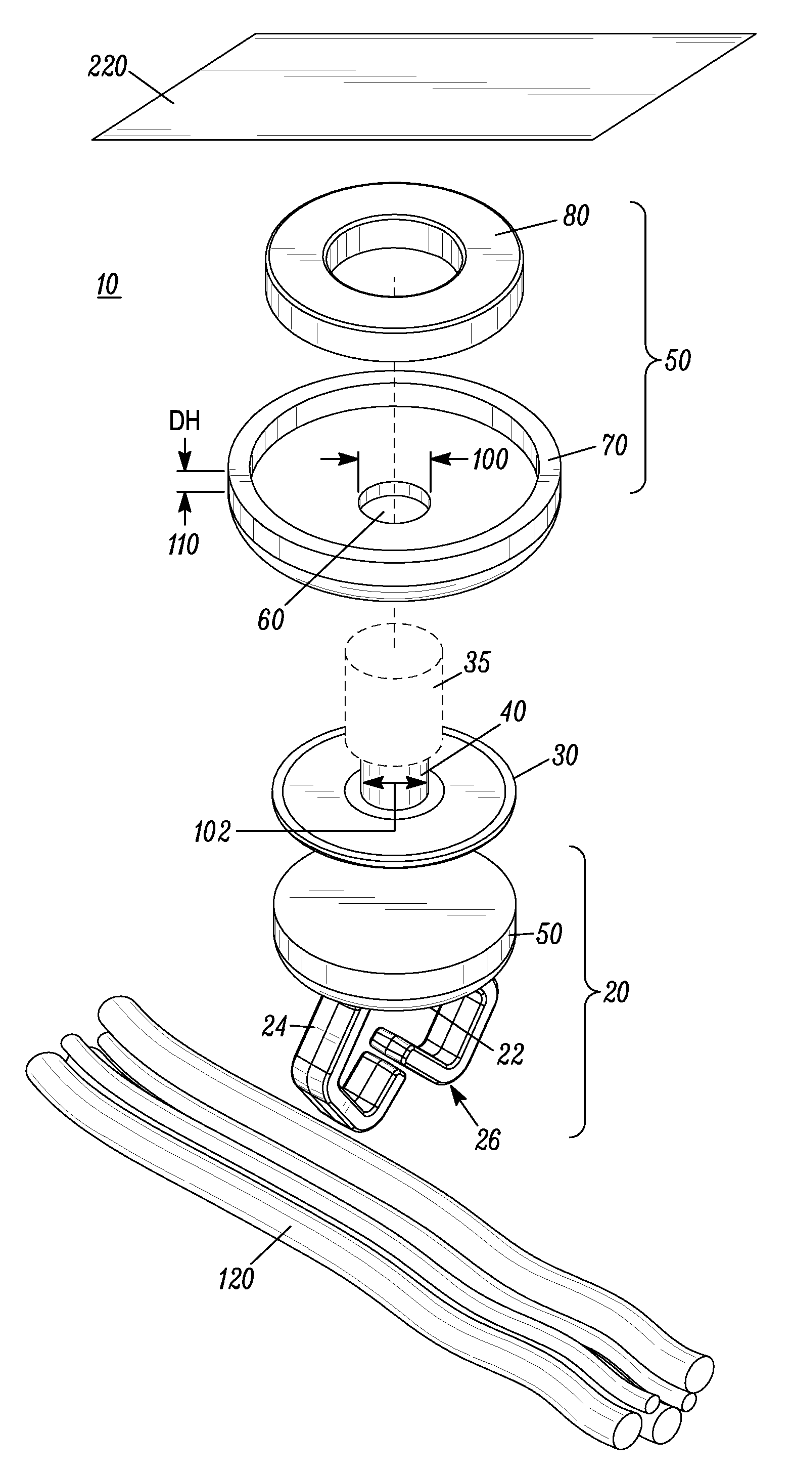
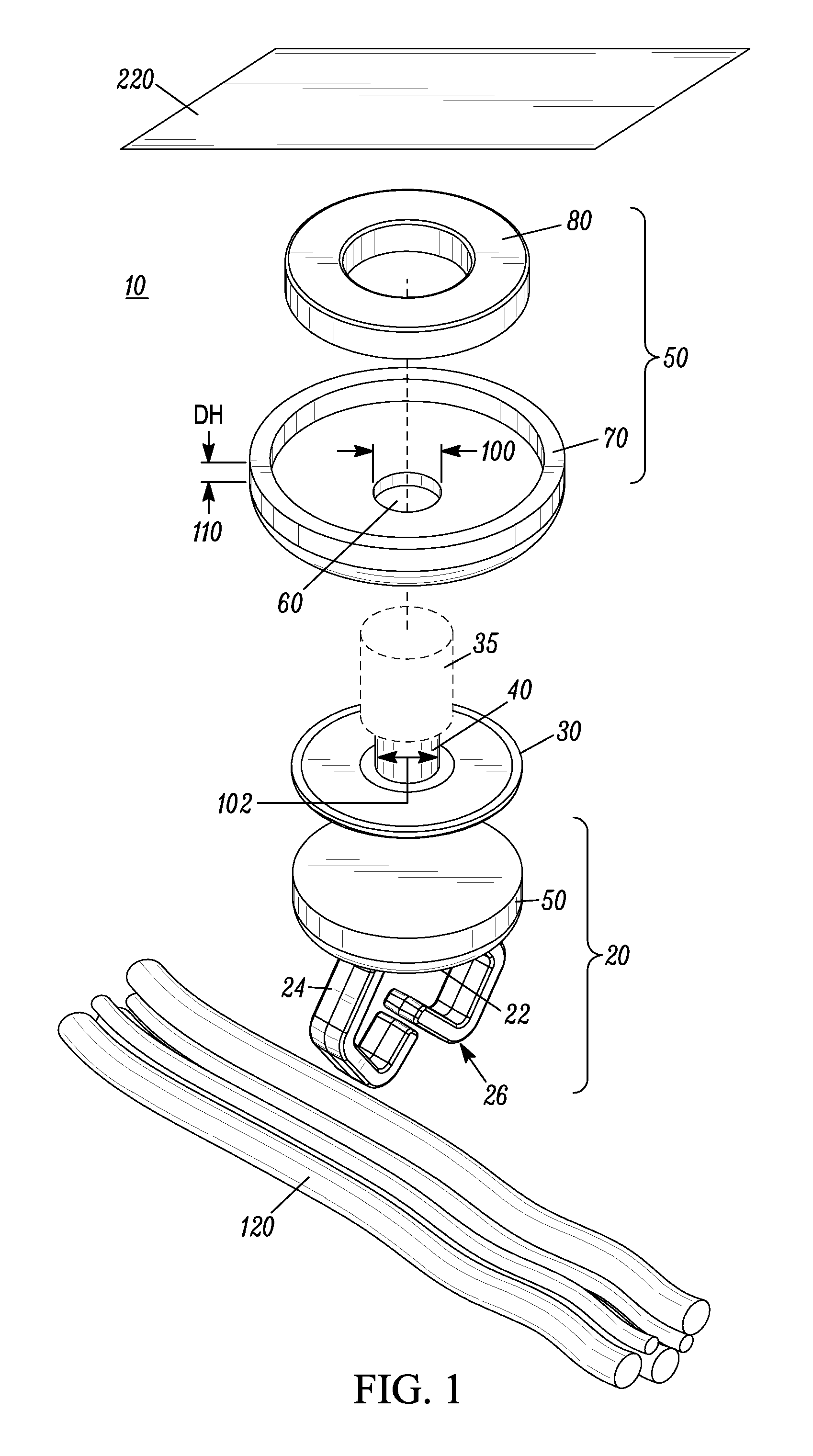
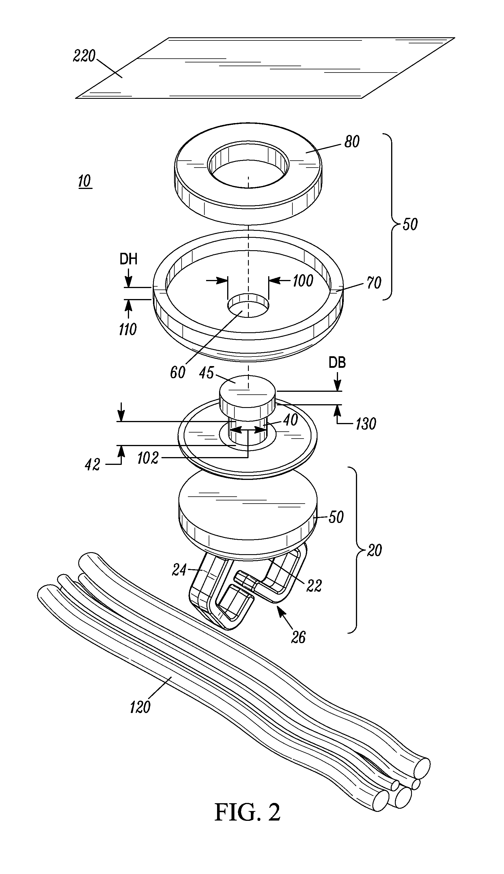
[0018]A magnetic cable fastener includes a magnetic fastener, a boss, a base, and a loop coupler attached to the base. The loop coupler is attached to the base and is operable to attach to another structure. The loop coupler may be a cable, wires, electrical conduit, rope, adjustable strap, and a tie wrap or suitable object. According to one embodiment, the loop coupler may further include at least two fingers. The fingers are operative to flex or compress appropriately to permit the cables to enter the fingers. According to another embodiment, the loop coupler is a solid loop to permit for example, a cable strap to be inserted and attach the cable strap to the loop coupler. The magnetic fastener has a hole with suitable shape and / or diameter to adjustably fasten with the boss or alternatively with at least one ratchet to adjustably fasten the magnetic fastener. Thus, the magnetic cable fastener may secure one or more cables via the loop fingers or solid loop or other suitable cable...


PUM


Abstract

A magnetic cable fastener includes a magnetic fastener, a boss, a base, and a loop coupler attached to the base. The loop coupler is attached to the base and is operable to attach to another structure. The loop coupler may be a cable, wires, electrical conduit, rope, adjustable strap, and a tie wrap or suitable object. According to one embodiment, the loop coupler may further include at least two fingers. The fingers are operative to flex or compress appropriately to permit the cables to enter the fingers. According to another embodiment, the loop coupler is a solid loop to permit for example, a cable strap to be inserted and attach the cable strap to the loop coupler. Thus, the magnetic cable fastener may secure one or more cables via the loop fingers or solid loop or other suitable cable coupler.

Description

RELATED APPLICATIONS[0001]This is a continuation in part application claiming priority from an application entitled “Magnetic Bracket and Method” having a docket number P055D and a Ser. No. 13 / 831,525, and having a filing date of Mar. 14, 2013, the entire disclosure of which is incorporated herein by reference.[0002]Which is a continuation in part application claiming priority from an application entitled “Magnetic Fastener Clip” having a docket number P055 and a Ser. No. 12 / 464,867, and having a filing date of May 13, 2009, now U.S. Pat. No. 8,615,852 the entire disclosure of which is incorporated herein by reference.[0003]Co-Pending patent application entitled “Magnetic Bracket and Method” having a docket number POSSE and serial number TBD having a filing date the same as this patent application the entire disclosure of which is incorporated herein by reference.FIELD OF THE INVENTION[0004]The invention relates generally to devices for fastening objects, and more particularly to a ...

Claims


Application Information

Patent Timeline
Patent Type & Authority Applications(United States)
IPC IPC(8): F16L3/12B60R16/02F16B1/00F16L3/13F16M13/02
CPCF16L3/12F16M13/022F16B1/00F16B2001/0035F16L3/1222B60R16/0215F16L3/13H02G3/32F16G11/143F16B5/0685F16G11/048F16B2200/83
Inventor DICKINSON, DANIEL JAMESSMITH, MICHAEL WALTER
Owner TERMAX CORP
Why Eureka
Try Eureka