Super surface-based small-scale microwave frequency-reconfigurable coupler

A microwave frequency and coupler technology, used in waveguide-type devices, electrical components, connecting devices, etc., can solve the problems of small tuning range, high cost, and high loss, reducing loss, increasing frequency tuning range, and low loss. Effect

Inactive Publication Date: 2017-06-23
UNIV OF ELECTRONIC SCI & TECH OF CHINA
View PDF2 Cites 2 Cited by
  • Summary
  • Abstract
  • Description
  • Claims
  • Application Information

AI Technical Summary

Problems solved by technology

[0004] What the present invention aims to solve are the technical problems of l

Method used


Image

  • Super surface-based small-scale microwave frequency-reconfigurable coupler
  • Super surface-based small-scale microwave frequency-reconfigurable coupler
  • Super surface-based small-scale microwave frequency-reconfigurable coupler

Examples


Embodiment 1

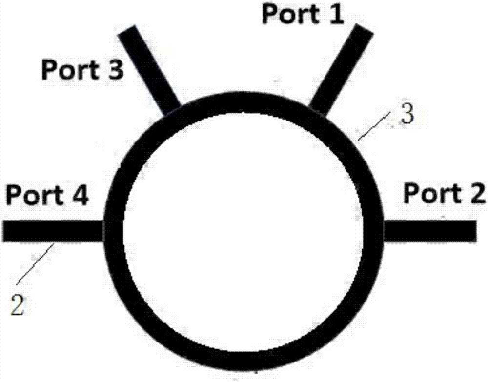
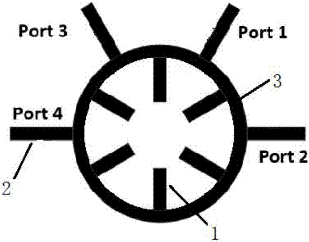
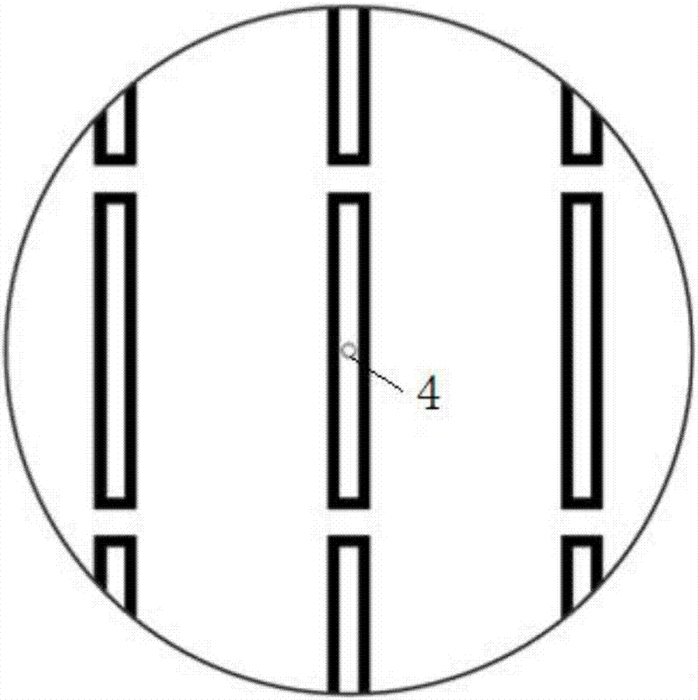
[0039] This implementation provides a small microwave frequency reconfigurable coupler based on metasurfaces, including an upper circular structure with equal radius and thickness, a lower circular structure, and the upper circular structure and the lower circular structure pass through the center of the circle set at the center of the circle The hole 4 and the metal rod set through the center hole 4 realize structural fixation and relative angle tuning; the upper surface of the upper circular structure is a metasurface; the upper surface of the lower circular structure is fixed with a ring coupler, and the lower surface is a contact ground. Such as image 3 , the metasurface consists of periodically distributed rectangular metallic ring structures. The specific structure of the rectangular metal ring structure is as follows Figure 4 .

[0040] To analyze the tunable properties of the metasurface, this embodiment adopts the classical analysis method of metamaterials, assumi...

Embodiment 2

[0053] In this embodiment, on the basis of Embodiment 1, the ring coupler part in the lower circular structure of the small microwave frequency reconfigurable coupler is further optimized.

[0054] On the basis of Embodiment 1, a microstrip stub line is added to the ring coupler. Such as Figure 5 , the center of the microstrip branch line 2 is provided with a microstrip stub line for impedance matching, which is used to improve the degree of freedom of impedance matching. The microstrip stub line is located at the microstrip branch line 2, and all the microstrip stub lines are distributed in one direction, which can be distributed counterclockwise or clockwise at the same time. By setting the microstrip stub line for impedance matching, the standing wave coefficient of the ring coupler is smaller and the energy loss is less.

[0055] Preferably, when the microstrip branch lines 2 are equal, the impedance of the two branch lines is equal, and the matching effect is better. ...


PUM

PropertyMeasurementUnit
Circumferenceaaaaaaaaaa
Thicknessaaaaaaaaaa

Abstract

The present invention relates to a super surface-based small-scale microwave frequency-reconfigurable coupler, which mainly solves the technical problems of large size, high cost, high loss and small tuning range in the prior art. According to the technical scheme of the invention, the super surface-based small-scale microwave frequency-reconfigurable coupler is composed of an upper-layer circular structure and a lower-layer circular structure, wherein the upper-layer circular structure and the lower-layer circular structure are the same in both radius and thickness. The upper-layer circular structure and the lower-layer circular structure are structurally fixed and tuned at a relative angle through a center hole (4) arranged at the circle centers of the upper-layer circular structure and the lower-layer circular structure, and a metal rod arranged to penetrate through the center hole (4). The upper surface of the upper-layer circular structure is a super surface. An annular coupler is fixedly attached to the upper surface of the lower-layer circular structure. The lower surface of the lower-layer circular structure is a ground plane. In this way, the above technical problems in the prior art are well solved. The super surface-based small-scale microwave frequency-reconfigurable coupler can be applied to the industrial production of microwave frequency-reconfigurable couplers.

Description

technical field [0001] The invention relates to the technical field of microwave devices, in particular to a metasurface-based small microwave frequency reconfigurable coupler. Background technique [0002] In today's multi-frequency and multi-standard mobile wireless systems, transceivers are mostly implemented by integrating multiple single-frequency or single-standard RF front-ends and sharing part of the analog baseband processing circuits in parallel. As the operating frequency bands and standards increase, the on-chip silicon area and the number of off-chip passive components in traditional multi-band and multi-standard transceivers increase, resulting in larger system size, increased design cost, increased system power consumption, and increased battery life shortening etc. As a basic component in microwave communication systems, couplers are widely used in microwave circuits such as balanced amplifiers, mixers, and feed networks for antenna arrays. In order to meet...

Claims


Application Information

Patent Timeline
IPC IPC(8): H01P5/18
CPCH01P5/18H01P5/184
Inventor 陈会万应禄石宪青朱磊
Owner UNIV OF ELECTRONIC SCI & TECH OF CHINA
Why Eureka
Try Eureka