
Miniaturized multilayer hybrid-phase signal splitter circuit

a splitter circuit and multi-layer technology, applied in the field of millimeterwave (mmw) circuit technology, can solve the problems of generating a pair of opposite-phase output signals, inability to provide a pair of in-phase output signals, and inconvenient use of miniaturized integrated circuitry, and achieve the effect of reducing the size of ic implementation

Active Publication Date: 2011-09-06
NAT TAIWAN UNIV
View PDF3 Cites 2 Cited by
  • Summary
  • Abstract
  • Description
  • Claims
  • Application Information

AI Technical Summary

Benefits of technology

[0013]It is therefore an objective of this invention to provide a miniaturized multilayer hybrid-phase signal splitter circuit whose signal processing function is fully equivalent to a conventional rat-race coupler but with a reduced smaller size that allows miniaturized IC implementation.
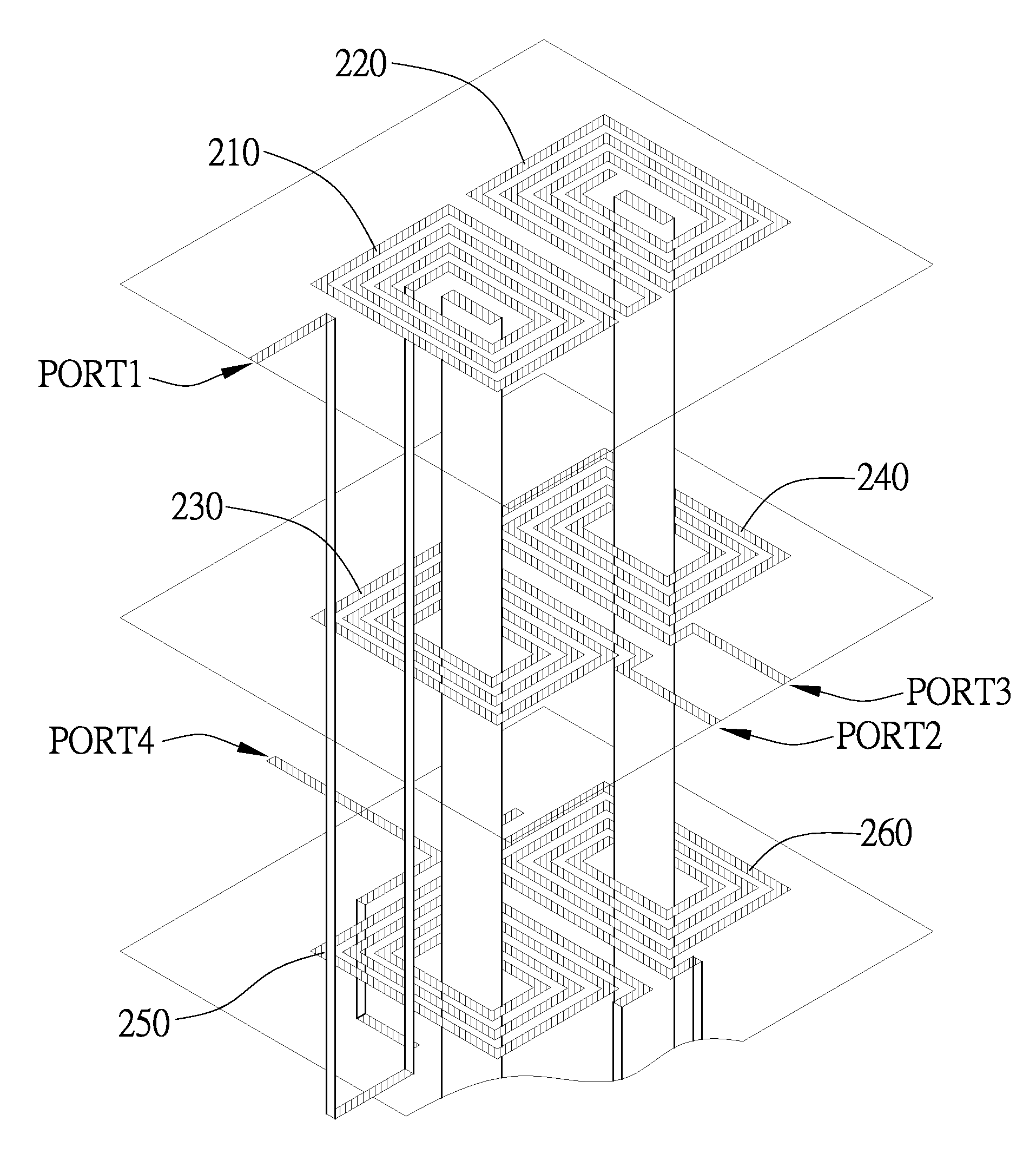
[0017]Compared to the conventional rat-race coupler, the invention has the advantage of a miniaturized size for IC implementation due to the use of the multilayer substrate (3-layer substrate) for the layout of 6 transmission lines and a spiral topology for the patterning of these 6 transmission lines. Specifically speaking, the required layout area for the invention is only about 10% of the layout area for the conventional rat-race coupler.

Problems solved by technology

One drawback to the rat-race coupler, however, is that it has a relatively bulky size that makes it unsuitable for use in miniaturized integrated circuitry.
One drawback to this patent, however, is that it can only generate a pair of opposite-phase output signals and cannot provide a pair of in-phase output signals, and therefore cannot be used in place of the rat-race coupler.
However, similar to the aforementioned patent, this patent can only generate a pair of opposite-phase output signals and cannot provide a pair of in-phase output signals, and therefore cannot be used in place of the rat-race coupler.
However, this improved rat-race coupler is nonetheless relatively bulky in size for miniaturized IC implementation.

Method used


Image

  • Miniaturized multilayer hybrid-phase signal splitter circuit
  • Miniaturized multilayer hybrid-phase signal splitter circuit
  • Miniaturized multilayer hybrid-phase signal splitter circuit

Examples


Embodiment Construction

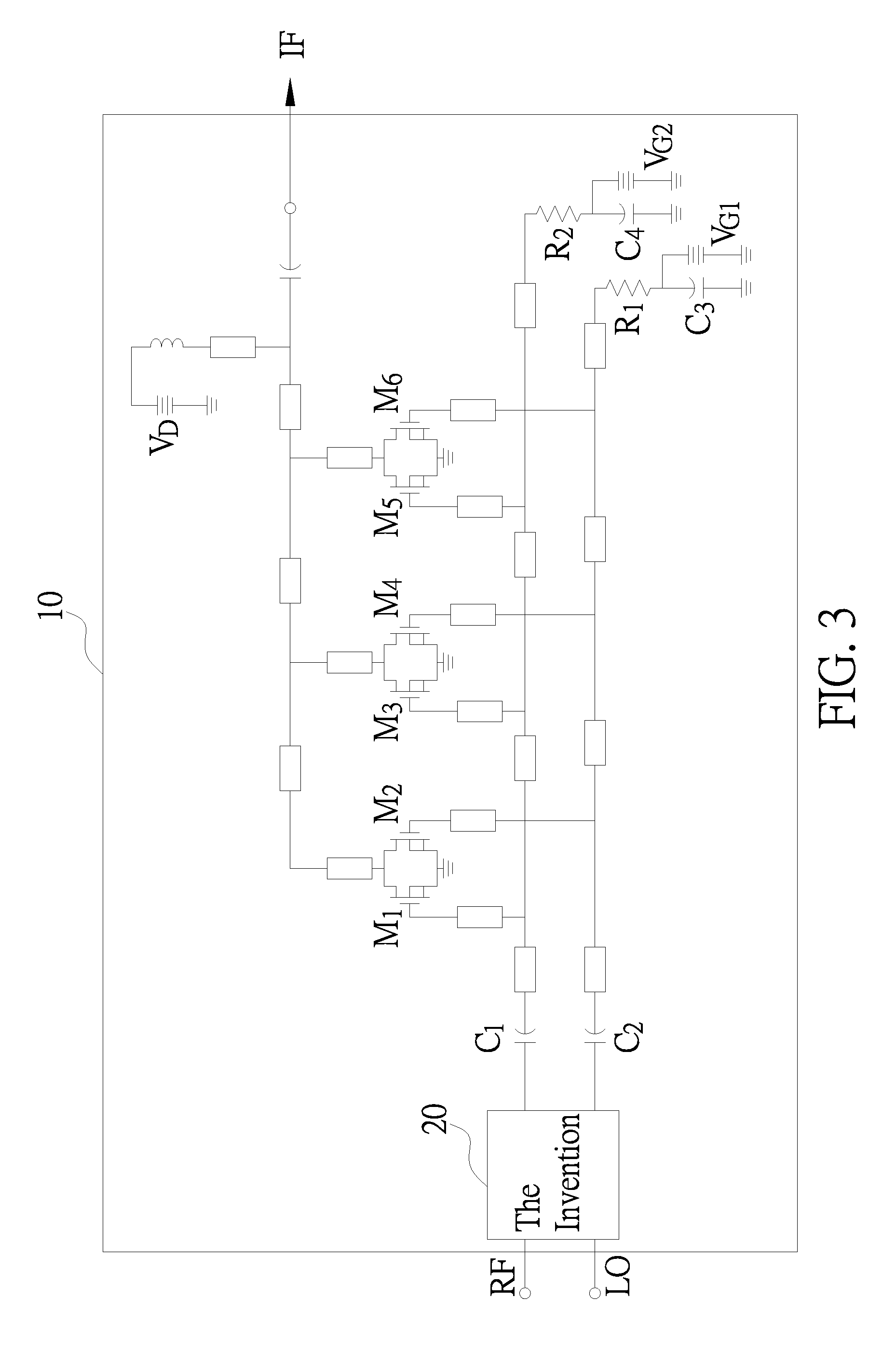
[0029]The miniaturized multilayer hybrid-phase signal splitter circuit according to the invention is disclosed in full details by way of preferred embodiments in the following with reference to the accompanying drawings. The invention is hereinafter referred to in short as “hybrid-phase signal splitter circuit”.

Function and Application of the Invention

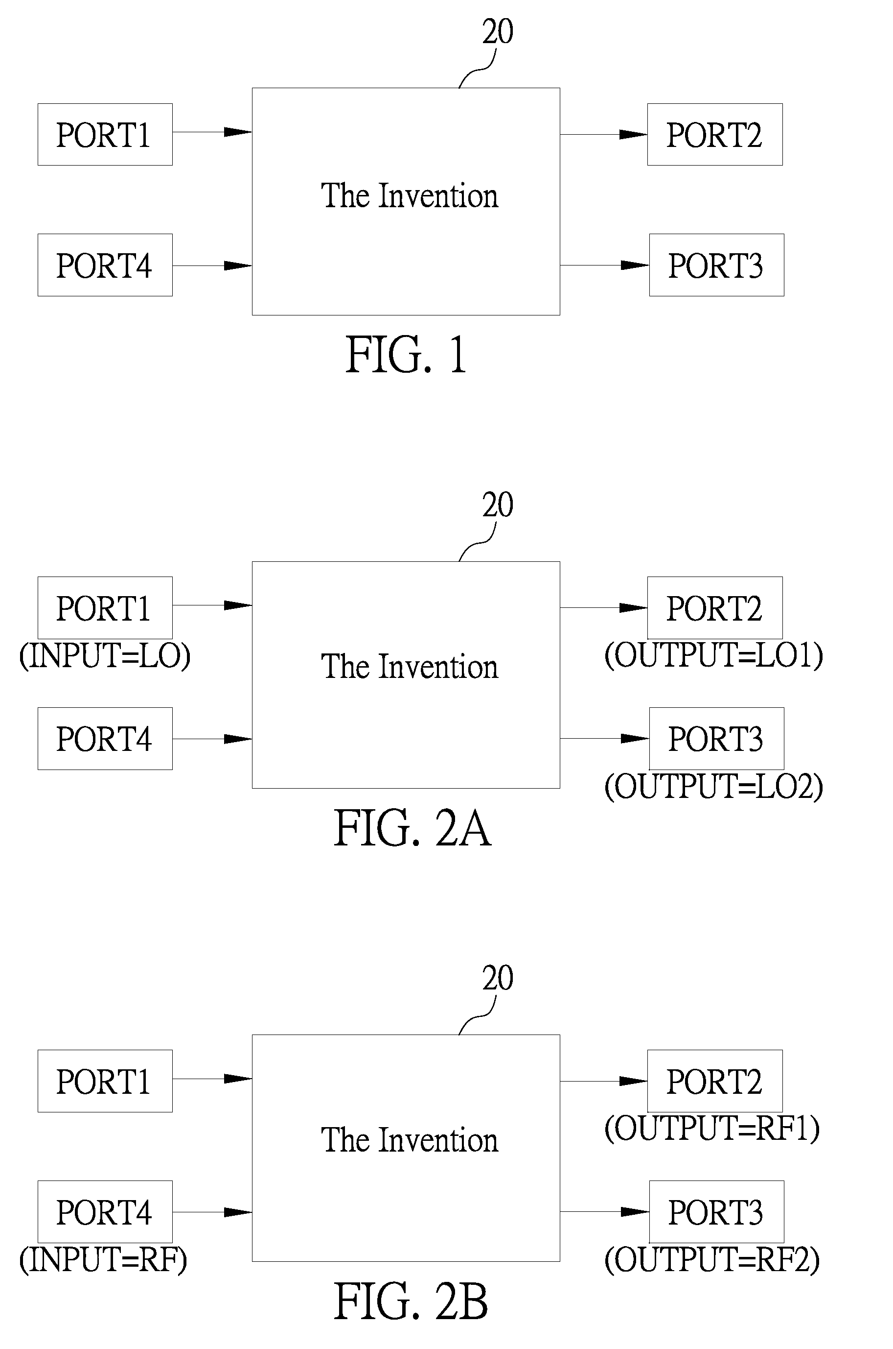
[0030]In application, the hybrid-phase signal splitter circuit of the invention 20 is fully equivalent in function to a conventional rat-race coupler, except with a different architecture that can be implemented with a miniaturized size. FIG. 1 and FIGS. 2A-2B show the I / O (input / output) functional model of the hybrid-phase signal splitter circuit of the invention 20.

[0031]Referring first to FIG. 1, the hybrid-phase signal splitter circuit of the invention 20 has an I / O interface including a first port PORT1, a second port PORT2, a third port PORT3, and a fourth port PORT4.

[0032]Referring next to FIG. 2A, in operation, when the first p...


PUM


Abstract

A miniaturized multilayer hybrid-phase signal splitter circuit is proposed, which is fully equivalent in function to a conventional rat-race coupler, but with a specialized circuit layout structure that allows its IC implementation to be more miniaturized than the conventional rat-race coupler. The proposed hybrid-phase signal splitter circuit features the use of a multilayer substrate for the layout of six transmission lines in such a manner that the transmission lines in the middle layer are inductively coupled to the transmission lines on the overlying layer as well as the transmission lines on the underlying layer to form a Marchand balun. In IC implementation, the required layout area is only about 10% of the layout area for the conventional rat-race coupler.

Description

BACKGROUND OF THE INVENTION[0001]1. Field of the Invention[0002]This invention relates to millimeter-wave (MMW) circuit technology, and more particularly, to a miniaturized multilayer hybrid-phase signal splitter circuit whose signal processing function is fully equivalent to a conventional rat-race coupler, but having a specialized circuit layout structure that allows its IC implementation to be more miniaturized than the conventional rat-race coupler.[0003]2. Description of Related Art[0004]Rat-race couplers are also referred to as hybrid-phase ring couplers which are typically used as a circuit component in a millimeter-wave (MMW) mixer. In operation, the rat-race coupler receives the input of a carrier signal RF and the input of a local oscillation signal LO and splits the RF signal into a pair of in-phase output signals (i.e., phase difference is 0 degree) and also splits the LO signal into a pair of opposite-phase output signals (i.e., phase difference is 180 degrees) which ca...

Claims


Application Information

Patent Timeline
Patent Type & Authority Patents(United States)
IPC IPC(8): H01P5/12H03H7/18H01P1/18
CPCH01P5/187
Inventor KUO, CHUN-LINKUO, CHE-CHUNGWANG, HUEI
Owner NAT TAIWAN UNIV
Learn More