Method and System for Ladar Transmission Employing Dynamic Scan Patterns with Macro Patterns and Base Patterns

a dynamic scan and ladar technology, applied in distance measurement, surveying and navigation, instruments, etc., can solve the problems of large size, large weight, and large power requirements, and the conventional ladar solution for computer vision problems suffers from high cost, large data bandwidth use, and large data bandwidth us

Active Publication Date: 2016-02-18
AEYE INC
View PDF2 Cites 123 Cited by
  • Summary
  • Abstract
  • Description
  • Claims
  • Application Information

AI Technical Summary

Problems solved by technology

However, conventional ladar solutions for computer vision problems suffer from high cost, large size, large weight, and large power requirements as well as large data bandwidth use.
These complicating factors have largely limited their effective use to costly applications that require only short ranges of vision, narrow fields-of-view and / or slow revisit rates.
However, these conventional systems are believed to suffer from a number of shortcomings.
For example, flash ladar systems require a very high energy per pulse laser, which is not only costly but can also be an eye hazard.
Furthermore, the read-out integrated circuits for flash ladar systems are typically quite noisy, optically and electronically.
Also, the wide field-of-view signal-to-noise ratio (SNR) for flash ladar systems is typically very low, which results in short ranges, thereby detracting from their usefulness.
While conventional scanning ladar solves many of the problems experienced in connection with flash ladar, conventional scanning ladar systems typically suffer from bulkiness and frame rate limitations.

Method used


Image

  • Method and System for Ladar Transmission Employing Dynamic Scan Patterns with Macro Patterns and Base Patterns
  • Method and System for Ladar Transmission Employing Dynamic Scan Patterns with Macro Patterns and Base Patterns
  • Method and System for Ladar Transmission Employing Dynamic Scan Patterns with Macro Patterns and Base Patterns

Examples


example beam

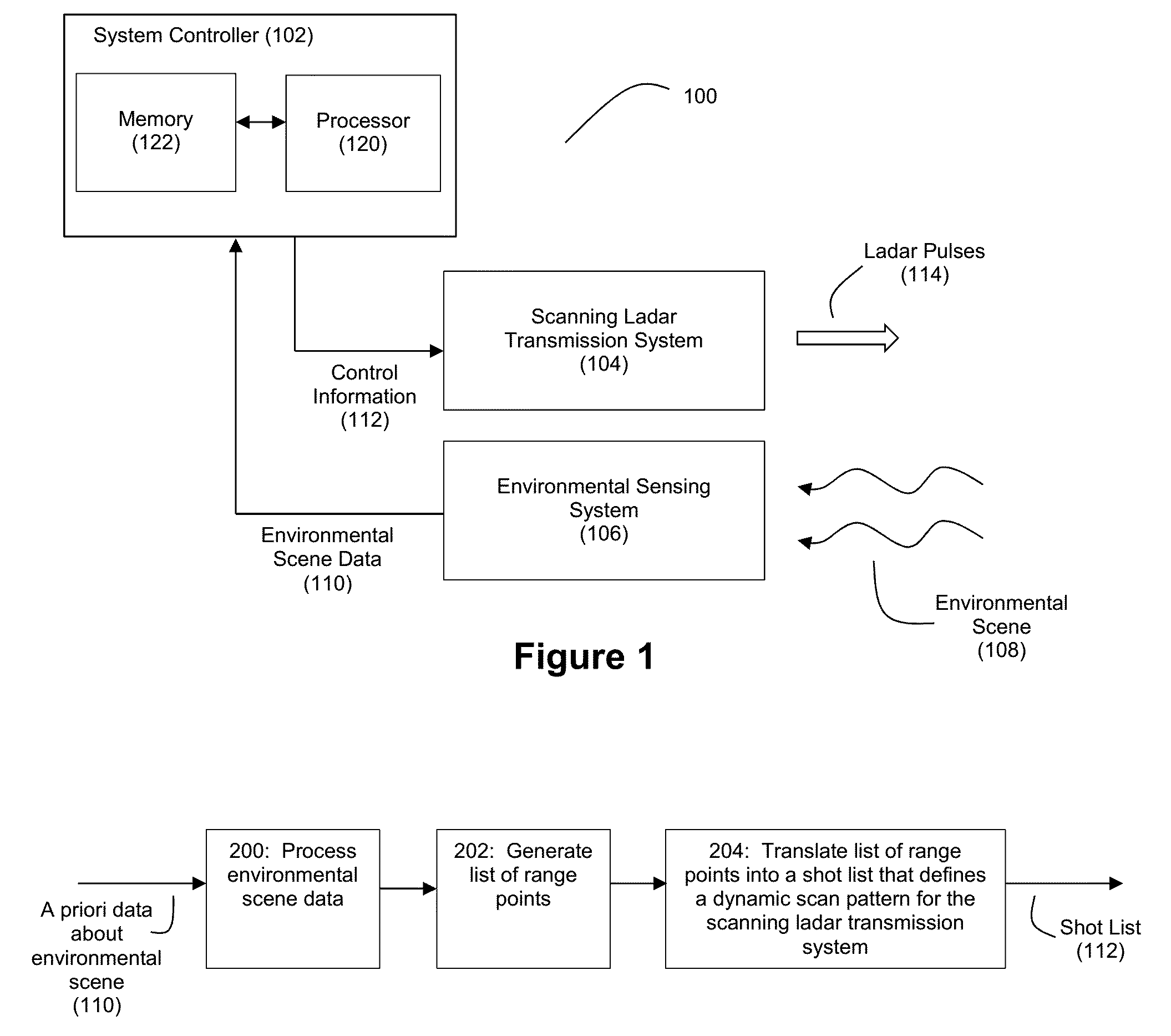
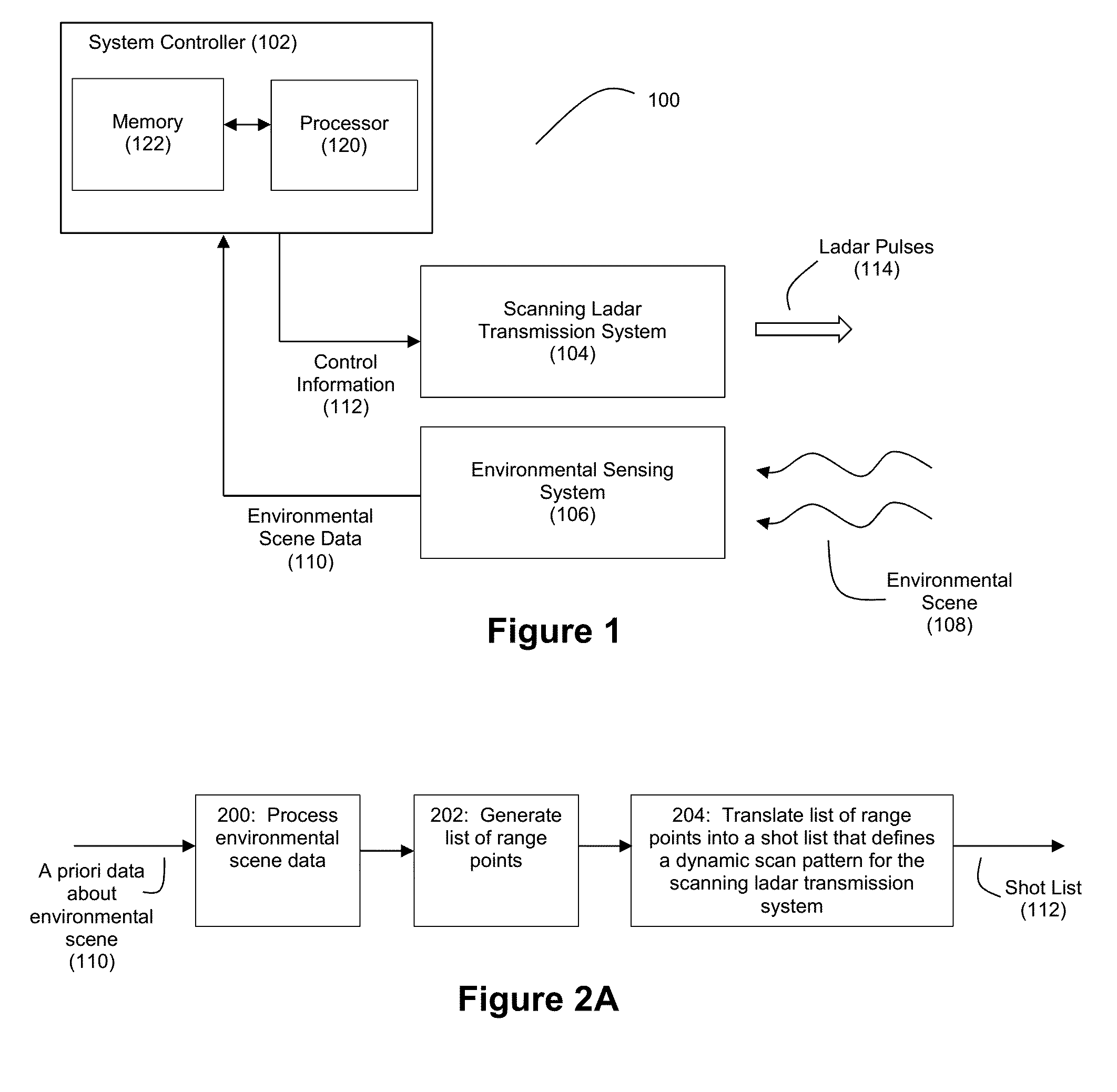
Scanner Controller 308

[0150]FIG. 10 depicts an example embodiment for a beam scanner controller 308 that can be used in connection with driving dual MEMS mirrors 500 / 502 in instances where the shot list includes interline skipping and interline detours. To provide acceleration, the beam scanner controller 308 can take the form of a field programmable gate array (FPGA) with logic deployed thereon as shown in connection with FIG. 10. By leveraging the parallelism that is supported by the reconfigurable hardware logic of an FPGA, the beam scanner controller 308 can operate in an accelerated manner. However, other platforms could be used for the beam scanner controller, including but not limited to microprocessors, ASICs, and the like.

[0151]In the example embodiment of FIG. 10, the beam scanner controller receives a range point list 240 as input via FIFO2. FIFO1 can be used to store fire commands and associated pulse patterns for each fire command. The pulse patterns can be ordered with...


PUM


Abstract

Various embodiments are disclosed for improved scanning ladar transmission, including but not limited to an example embodiment where a dynamic scan pattern for a scanning ladar transmission system includes a macro pattern having a base pattern embedded therein.

Description

CROSS-REFERENCE AND PRIORITY CLAIM TO RELATED PATENT APPLICATIONS[0001]This patent application claims priority to U.S. provisional patent application Ser. No. 62 / 038,065, filed Aug. 15, 2014, the entire disclosure of which is incorporated herein by reference.[0002]This patent application is related to the following patent applications: (1) U.S. patent application Ser. No. ______, entitled “Method and System for Ladar Transmission with Closed Loop Feedback Control of Dynamic Scan Patterns”, filed this same day and identified by Thompson Coburn Attorney Docket Number 56976-147513, (2) U.S. patent application Ser. No. ______, entitled “Method and System for Ladar Transmission with Spinning Polygon Mirror for Dynamic Scan Patterns”, filed this same day and identified by Thompson Coburn Attorney Docket Number 56976-147514, (3) U.S. patent application Ser. No. ______, entitled “Method and System for Ladar Transmission with Interline Skipping for Dynamic Scan Patterns”, filed this same day...

Claims


Application Information

Patent Timeline
Patent Type & Authority Applications(United States)
IPC IPC(8): G01S7/484G01S7/4861G01S17/10G01S17/86G01S17/87G01S17/89G01S17/931
CPCG01S17/10G01S7/484G01S17/42G01S7/4814G01S17/89G01S7/4817G01S7/499G01S17/86G01S17/931G01S7/4861G01S17/87
Inventor DUSSAN, LUIS, CARLOS
Owner AEYE INC
Why Eureka
Try Eureka