
Master-slave system with triggered remote function calls

a remote function and master-slave technology, applied in the field of master-slave systems, can solve the problems of requiring a new practical real-time configuration/control, too slow com link to support real-time function, and difficult to re-configure/update slave-side hardware function blocks,

Active Publication Date: 2016-02-18
TEXAS INSTR INC
View PDF8 Cites 10 Cited by
  • Summary
  • Abstract
  • Description
  • Claims
  • Application Information

AI Technical Summary

Benefits of technology

This patent describes a method for triggering software functions in a master-slave system. The master sends signals to the slave to trigger the functions, which then execute the functions using pre-loaded parameters. The slave can also have its own function block that can be configured to service the trigger signals. This method can provide efficient and flexible triggering of software functions in the system.

Problems solved by technology

For example, a master can integrate hardware function blocks such as hardware state machines or hardware accelerators that need to send real-time requests to slaves (including slave-side hardware function blocks) that are not practical over these com links because either these hardware blocks are not configured for the communication protocol, or these com links are too slow to support real-time function requests.
Also, a slave can integrate hardware function blocks such as phase locked loops and transmitter / receivers that require real-time configuration / control that again is not practical over these com links.
However, because customer requirements change, it can be problematic to re-configure / update slave-side hardware function blocks.
It is also problematic for traditional interrupt service routines to handle complex requests requiring a number of input parameters.

Method used


Image

  • Master-slave system with triggered remote function calls
  • Master-slave system with triggered remote function calls

Examples


Embodiment Construction

[0012]This Description and the Drawings constitute a Disclosure of a triggered remote function call methodology, such for a master / slave system including controlling slave side hardware functionality / configuration.

[0013]As used in this Disclosure, master / host and slave are generic for networked devices configured to implement a triggered remote function call methodology according to this Disclosure.

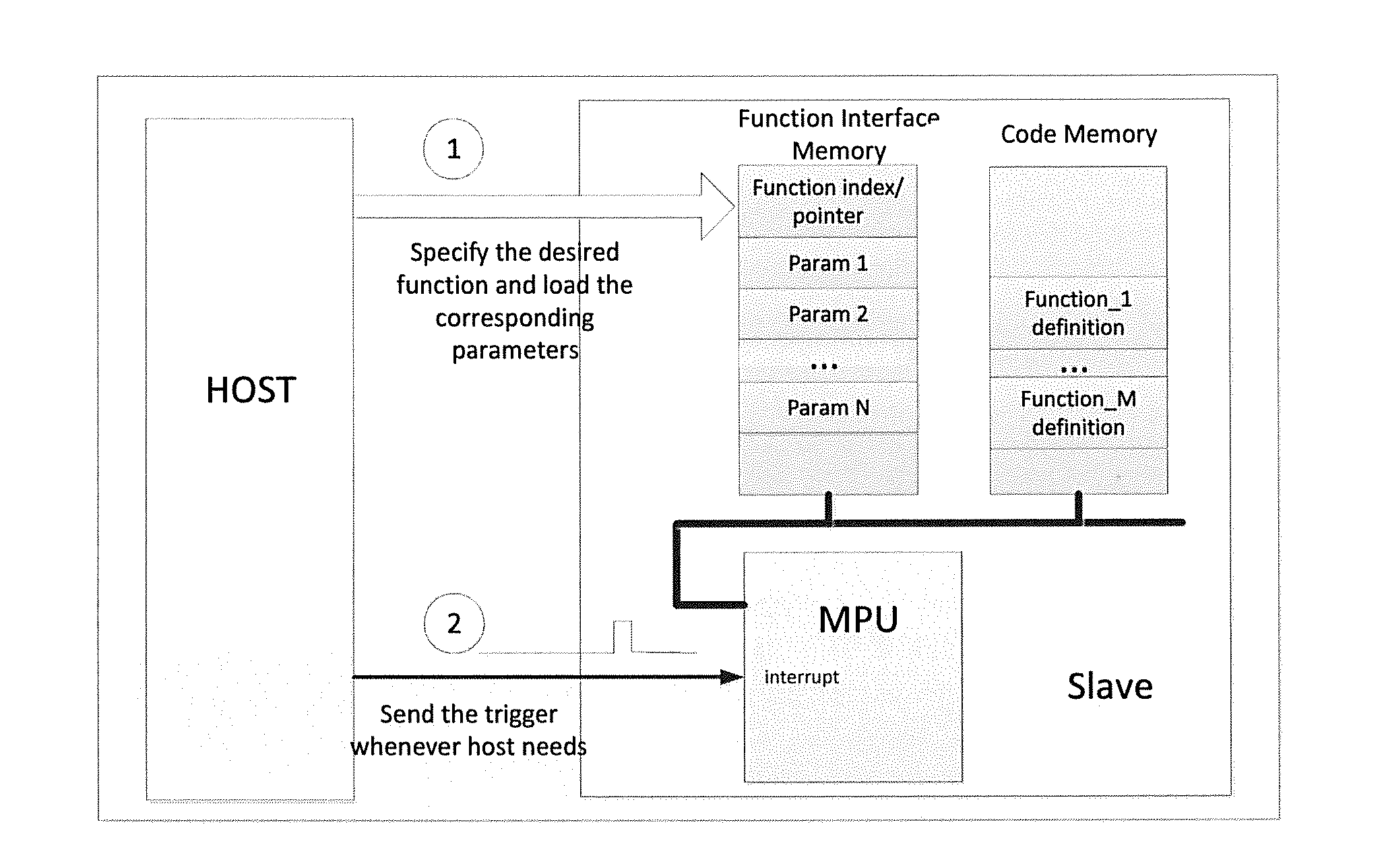
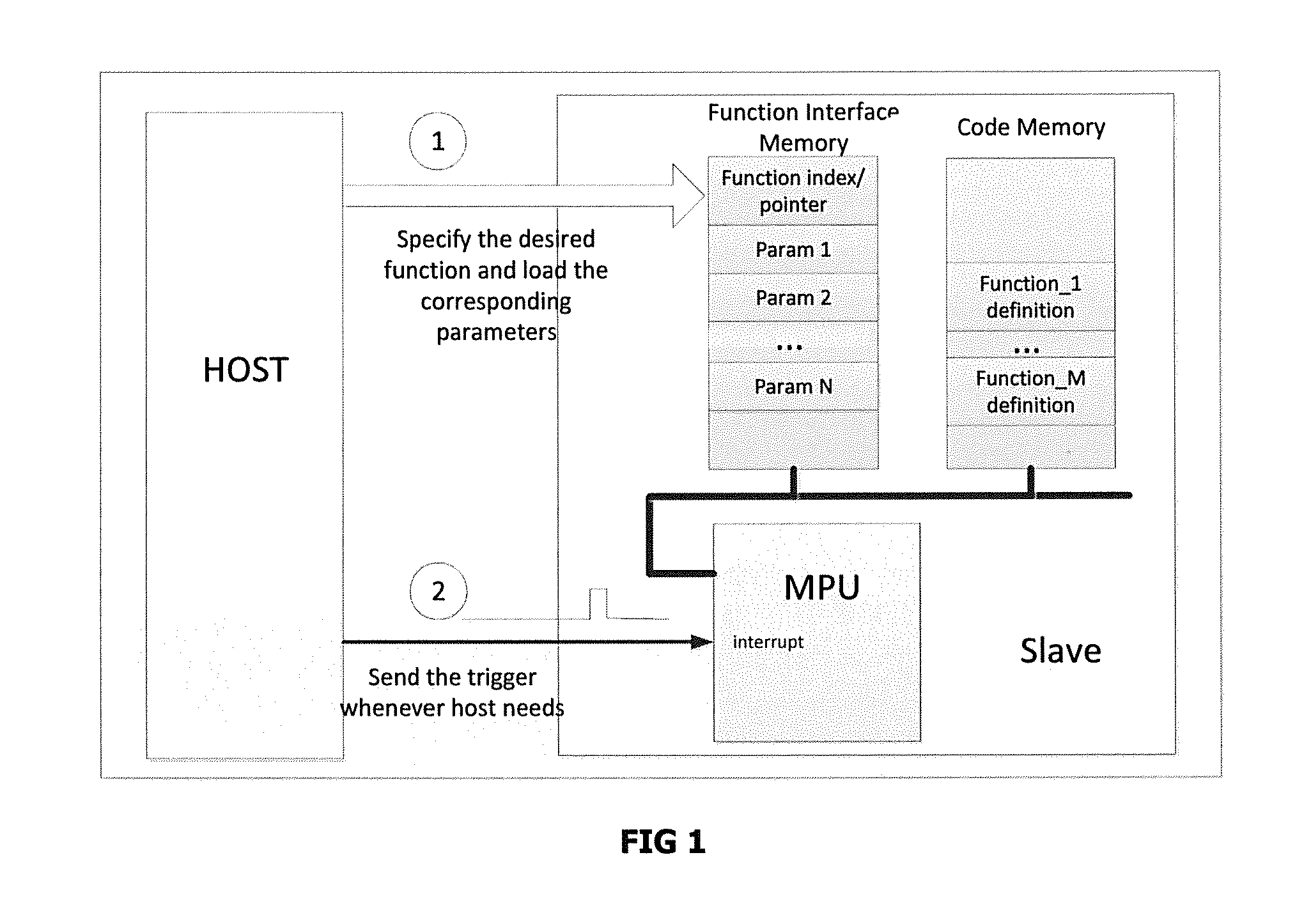
[0014]In brief overview, the Disclosed triggered remote function calls can be used in master-slave systems to trigger slave-side software functions pre-loaded by a master into slave MCU memory, with associated parameters pre-loaded into a slave function interface memory. A master issues trigger-function signals (such as rising / falling edges or signal levels) over a trigger-function signal line. The slave includes a trigger conditioning block that in response issues a trigger-function request to the slave MCU, which calls / executes the associated software function, including accessing the a...


PUM


Abstract

Triggered remote function calls can be used in master-slave systems to trigger slave-side software functions pre-loaded by a master into slave MCU memory, with associated parameters pre-loaded into a slave function interface memory. A master issues trigger-function signals (such as rising / falling edges or signal levels) over a trigger-function signal line. The slave includes a trigger conditioning block that in response issues a trigger-function request to the slave MCU, which calls / executes the associated software function, including accessing the associated trigger-function parameters from function interface memory. A slave can include a hardware function block with functionality configurable by a pre-loaded software configuration function (with associated parameters). A master can include a hardware function block configured to issue trigger-function signals. The slave (trigger conditioning block) can be configured to service trigger-function signals as an IRQ (interrupt request) to the MCU, which executes an ISR (interrupt service routine) as a triggered function call.

Description

CROSS-REFERENCE TO RELATED APPLICATIONS[0001]Priority is claimed under USC§119(e) to US Provisional Application 62 / 035,222 (Docket TI-75209PS), filed Aug. 8, 2014.BACKGROUND[0002]1 Technical Field.[0003]This Patent Document relates generally to master / host-slave systems, including slave configuration / function control.[0004]2. Related Art.[0005]In a master / host-slave system, a master / host processor commonly communicates with slave devices, such as MCU (microcontroller units) through a standardized communication bus, such as SPI, I2C (referred to as com links).[0006]System design flexibility for both masters and slaves can be enhanced by the integration of hardware function blocks requiring control, operation or configuration that is not practical over these com links. For example, a master can integrate hardware function blocks such as hardware state machines or hardware accelerators that need to send real-time requests to slaves (including slave-side hardware function blocks) that a...

Claims


Application Information

Patent Timeline
IPC IPC(8): G06F13/364G06F13/24G06F13/42
CPCG06F13/364G06F13/24G06F13/4282G06F13/124G06F9/4812
Inventor ZHANG, XIAOXIKLEMMER, NIKOLAUSCHOO, HUNSOO
Owner TEXAS INSTR INC
Learn More