
Method, charger device, and adaptor capable of maximum output power point tracking

Inactive Publication Date: 2016-02-18
MEDIATEK INC
View PDF14 Cites 16 Cited by
  • Summary
  • Abstract
  • Description
  • Claims
  • Application Information

AI Technical Summary

Benefits of technology

The present invention allows for a charger device to control the output power of an adaptor. This is done by adjusting the output voltage and current, which allows the adaptor to operate at its maximum output power point. This results in faster charging and reduces the overall waiting time for charging the battery.

Problems solved by technology

A traditional charging scheme may limit the level of input current provided from an adaptor for safety since different adaptors are designed with different rated output currents.
However, this also causes that the current from the adaptor is overly limited and the adaptor never outputs a larger current.
In this situation, the output power of adaptor becomes worse since the output power is almost limited by the traditional charging scheme.
Since the output power of an adaptor is limited, it is necessary for the traditional charging system to wait for a longer time period to charge the battery.
Additionally, adaptors designed with identical rated output currents may generate different variations on their output currents, and the traditional charging scheme limiting the output currents of these adaptors to the same level cannot adaptively control different types of adaptors.
Thus, the traditional charging scheme is not compatible with different types of adaptors.

Method used


Image

  • Method, charger device, and adaptor capable of maximum output power point tracking
  • Method, charger device, and adaptor capable of maximum output power point tracking
  • Method, charger device, and adaptor capable of maximum output power point tracking

Examples


first embodiment

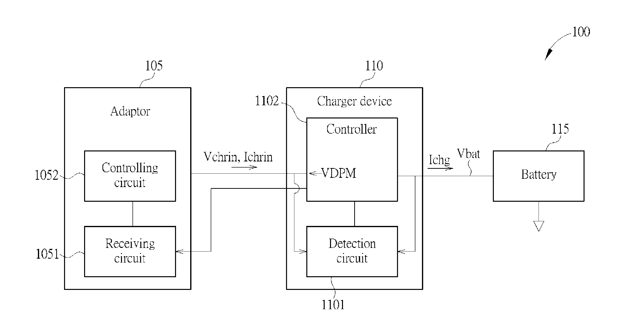
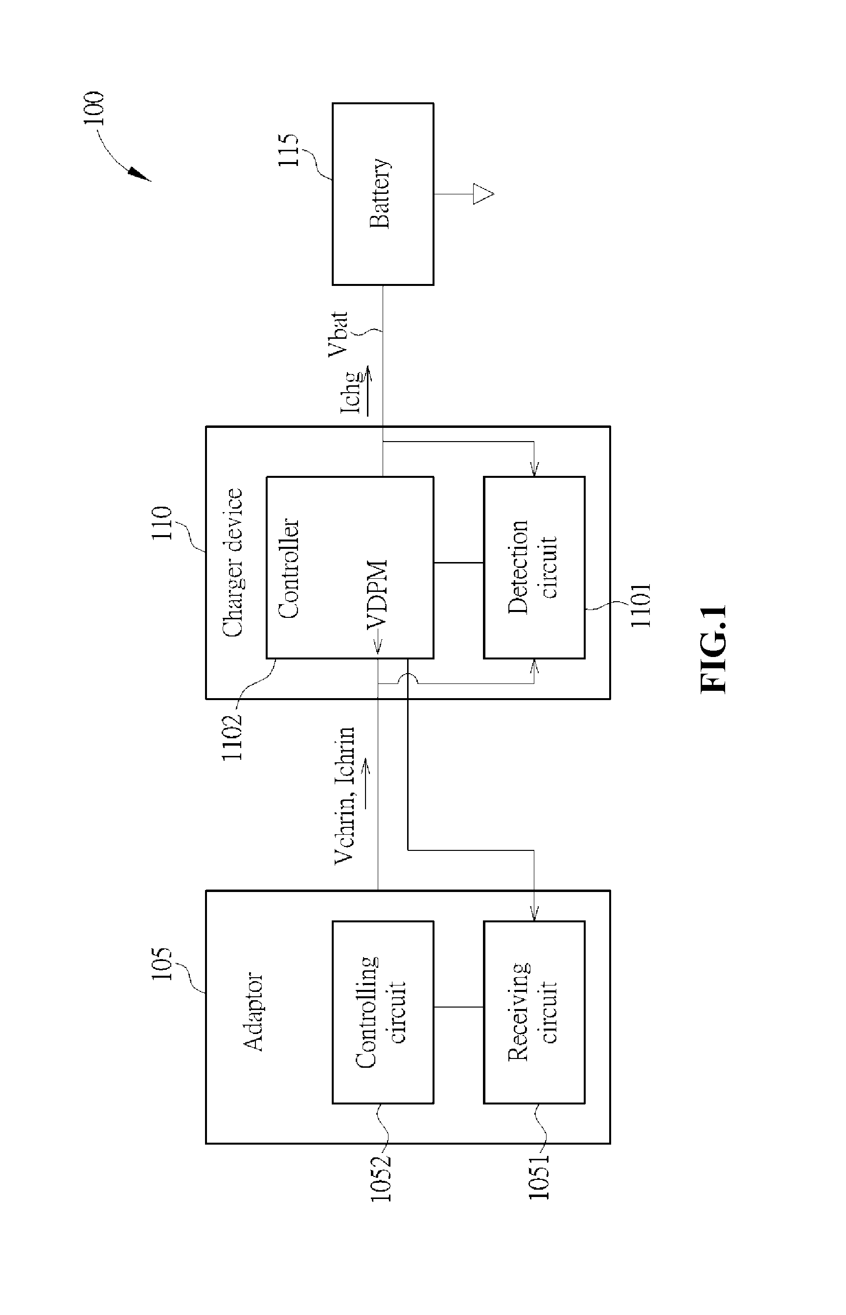
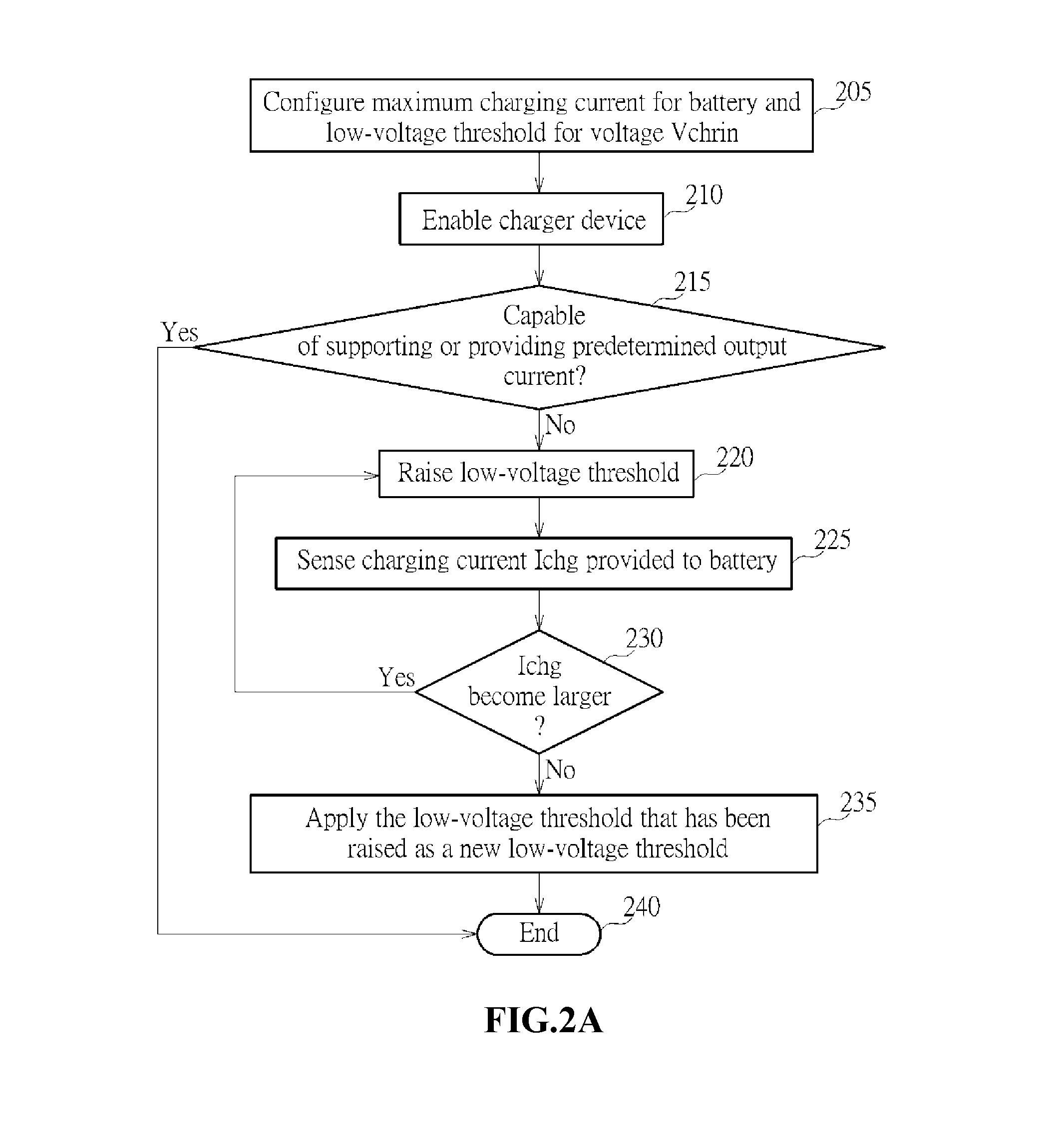
[0024]FIG. 2A is a flowchart illustrating the operations of charger device 110 according to the present invention. FIG. 2B is a diagram illustrating an example of output voltage curve of adaptor 105 according to the flowchart of FIG. 2A. FIG. 2C is a diagram illustrating an example of current curve of adaptor 105 according to the flowchart of FIG. 2A and the output voltage curve of FIG. 2B. Please refer to FIG. 2B. As shown in FIG. 2B, before time Ta, the charger device 110 tries to control the adaptor 105 to provide / output the predetermined current level, and the output voltage Vchrin of adaptor 105 is gradually lowered until the output voltage Vchrin reaches an initial level (e.g. 4.5 Volts) of low-voltage threshold VDPM at time Ta; in this example the adaptor 105 may be not capable of supporting / providing this predetermined current level. At time Ta, the controller 1102 is arranged to control the adaptor 105 to make the adaptor 105 raise its low-voltage threshold VDPM from the in...

second embodiment

[0037]Additionally, the controller 1102 can control and make the adaptor 105 to operate its maximum output power point by calculating the actual output powers of adaptor 105 and selecting the maximum output power to obtain the preferred working point of time Tmax; Ta′-Td′ shown in FIG. 3C are other working points of different times. FIG. 3A is a flowchart illustrating the operations of charger device 110 according to the present invention. FIG. 3B is a diagram illustrating an example of voltage curve of adaptor 105 according to the flowchart of FIG. 3A. FIG. 3C is a diagram illustrating an example of current curve of adaptor 105 according to the flowchart of FIG. 3A and the voltage curve of FIG. 3B. For example, the charger device 110 tries to control the adaptor 105 to provide / output a predetermined current level, and in this example the adaptor 105 is not capable of supporting / providing this predetermined current level. The controller 1102 controls the adaptor 105 to adjust the ou...


PUM


Abstract

A method for controlling an adaptor to charge a battery includes: determining whether the adaptor is capable of providing a predetermined charging current for the battery; sensing an output voltage of the adaptor and an output current of the adaptor; and controlling the adaptor to adjust the output current and the output voltage according to the sensed output voltage and the sensed output current when the adaptor is not capable of providing the predetermined charging current.

Description

FIELD OF INVENTION[0001]The present invention relates to a charging scheme, and more particularly to a method for controlling an adaptor to charge a battery.BACKGROUND OF THE INVENTION[0002]The market is flood with many different types of adaptors, and these different adaptors may be used for outputting / providing different rated currents. A traditional charging scheme may limit the level of input current provided from an adaptor for safety since different adaptors are designed with different rated output currents. Accordingly, the traditional charging scheme limits the level of current from an adaptor when the adaptor is connected and used for charging a battery. This can avoid that an adaptor may provide an over higher current. However, this also causes that the current from the adaptor is overly limited and the adaptor never outputs a larger current. For example, the traditional charging scheme may limit the level of current to 500 mA even though an adaptor may be capable of provi...

Claims


Application Information

Patent Timeline
IPC IPC(8): H02J7/00
CPCH02J7/0052H02J7/007H02J7/045H02J7/04H02J7/00714H02J7/007182H02J7/00
Inventor HSU, CHIH-YUANLEE, CHUAN-CHANG
Owner MEDIATEK INC
Features
  • Generate Ideas
  • Intellectual Property
  • Life Sciences
  • Materials
  • Tech Scout
  • Unparalleled Data Quality
  • Higher Quality Content
  • 60% Fewer Hallucinations
Learn More