Transmitter and method of transmitting

a technology of transmitting payload and transmitting method, which is applied in the direction of transmission path division, amplitude demodulation, signalling characterisation, etc., can solve the problems of reducing the robustness of each receiver, the bandwidth of each receiver, and the difficulty of a receiver to recover data, so as to improve the likelihood of recovering signalling data, improve the probability of detection, and improve the effect of robustness

Active Publication Date: 2016-02-18
SATURN LICENSING LLC
View PDF2 Cites 38 Cited by
  • Summary
  • Abstract
  • Description
  • Claims
  • Application Information

AI Technical Summary

Benefits of technology

[0009]According to one embodiment a number of sub-carriers used for the OFDM symbols carrying signalling data may be different from the number of sub-carriers used for the OFDM symbols which are used to carry the payload data. For example in order to improve a likelihood of recovering the signalling data, making it more robust for detection in more challenging radio environments the number of sub-carriers may be smaller than for the OFDM symbols carrying payload data. For example, the payload data bearing OFDM symbols may be required to have a high spectral efficiency and therefore for example the number of sub-carriers may be 16 k (16384) or 32 k (32768) whereas in order to improve a likelihood that a receiver can recover the signalling data from the signalling OFDM symbols, the number of sub-carriers for the first signalling OFDM symbol may be a lower number, for example, a 4k (4096) or 8 k (8192).

Problems solved by technology

However, there can also be a reduction in robustness in the sense that it may be more difficult for a receiver to recover data transmitted using a high number of sub-carriers compared to a smaller number of sub-carriers, because for a fixed transmission bandwidth, increasing the number of sub-carriers K also means reducing the bandwidth of each sub-carrier.
A reduction in the separation between sub-carriers can make demodulation of the data from the sub-carriers more difficult for example, in the presence of Doppler frequency shifts.

Method used


Image

  • Transmitter and method of transmitting
  • Transmitter and method of transmitting
  • Transmitter and method of transmitting

Examples


Embodiment Construction

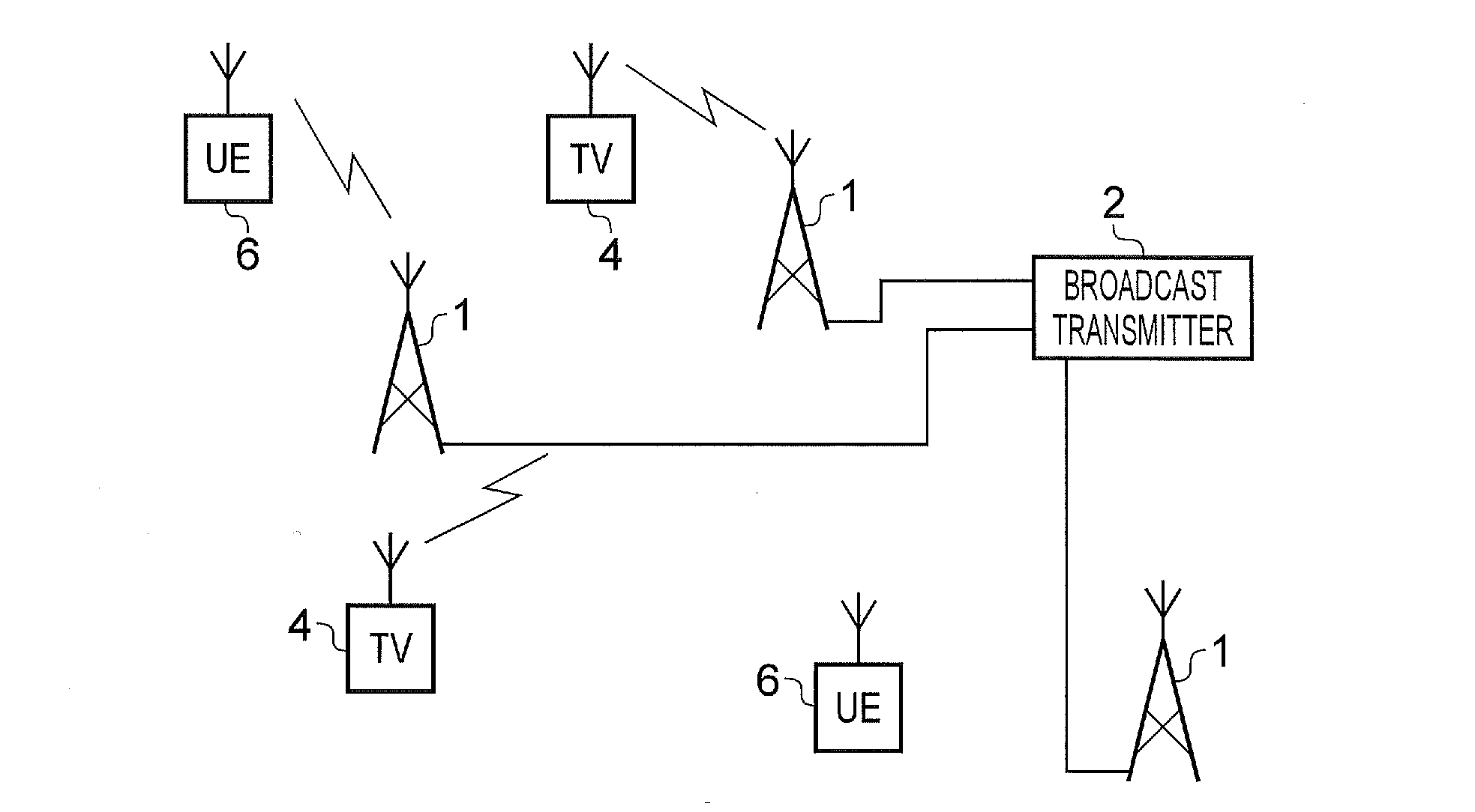
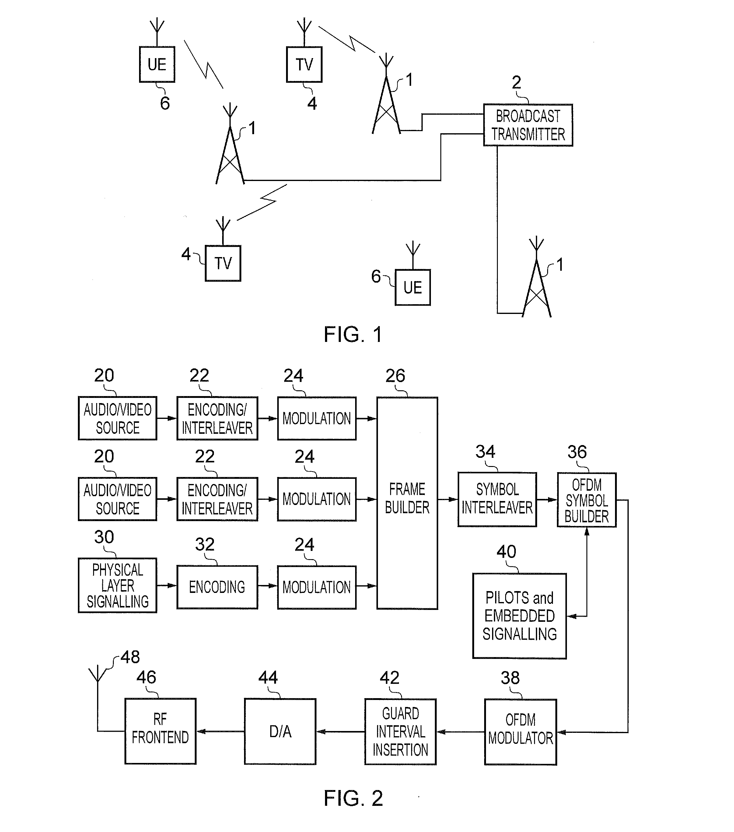
[0032]Embodiments of the present disclosure can be arranged to form a transmission network for transmitting signals representing data including video data and audio data so that the transmission network can, for example, form a broadcast network for transmitting television signals to television receiving devices. In some examples the devices for receiving the audio / video of the television signals may be mobile devices in which the television signals are received while on the move. In other examples the audio / video data may be received by conventional television receivers which may be stationary and may be connected to a fixed antenna or antennas.

[0033]Television receivers may or may not include an integrated display for television images and may be recorder devices including multiple tuners and demodulators. The antenna(s) may be inbuilt to television receiver devices. The connected or inbuilt antenna(s) may be used to facilitate reception of different signals as well as television ...


PUM


Abstract

A transmitter transmitting payload data using OFDM symbols includes a frame builder configured to receive the payload data and to receive signalling data for use in detecting and recovering the payload data at a receiver, and to form the payload data and the signalling data into frames for transmission. A modulator can modulate a first OFDM symbol with the signalling data forming a first of the frames and modulate one or more second OFDM symbols with the payload data forming one or more other frames, and a transmission unit transmits the first and second OFDM symbols. The first OFDM symbol is combined before transmission with a signature sequence that can be configured to allow for detection of the first OFDM symbol at the receiver and decoding the signalling data before the one or more second OFDM symbols carrying the payload data and at lower signal to noise ratios.

Description

FIELD OF THE DISCLOSURE[0001]The present disclosure relates to transmitters and methods of transmitting payload data using Orthogonal Frequency Division Multiplexed (OFDM) symbols.BACKGROUND OF THE INVENTION[0002]There are many examples of radio communication systems in which data is communicated using Orthogonal Frequency Division Multiplexing (OFDM). Systems which have been arranged to operate in accordance with Digital Video Broadcasting (DVB) standards for example, use OFDM. OFDM can be generally described as providing K narrow band sub-carriers (where K is an integer) which are modulated in parallel, each sub-carrier communicating a modulated data symbol such as Quadrature Amplitude Modulated (QAM) symbol or Quadrature Phase-shift Keying (QPSK) symbol. The modulation of the sub-carriers is formed in the frequency domain and transformed into the time domain for transmission. Since the data symbols are communicated in parallel on the sub-carriers, the same modulated symbols may b...

Claims


Application Information

Patent Timeline
Patent Type & Authority Applications(United States)
IPC IPC(8): H04L27/26H04L5/00
CPCH04L27/2634H04L5/001H04L27/2649H04L27/2602H04L27/2655H04L1/007H04L1/0072H04L5/0007H04L27/26524H04L27/2656H04L27/2657H04L27/2675H04L27/2613H04L1/0032H04L27/01H05K999/99
Inventor ATUNGSIRI, SAMUEL, ASANGBENG
Owner SATURN LICENSING LLC
Why Eureka
Try Eureka