System and method for artificial gravity fueled fluid dynamic energy generator or motor

a fluid dynamic energy generator and artificial gravity technology, applied in the direction of machines/engines, reaction engines, mechanical equipment, etc., can solve the problems of inefficient solar energy, inefficient use of centralized or distributed energy sources, and record high prices of supply and demand in highly volatile markets

Inactive Publication Date: 2016-02-25
PRILL ROBERT S
View PDF0 Cites 9 Cited by
  • Summary
  • Abstract
  • Description
  • Claims
  • Application Information

AI Technical Summary

Benefits of technology

[0005]The present invention includes an artificial gravity fueled fluid dynamic energy generator / motor comprising: a system control and brake assembly; a main bearing vertical shaft assembly connected to the system control and brake assembly; a platform connected to the main bearing vertical shaft assembly; a ratchet assembly connected to the main bearing vertical shaft assembly; a rotor connected to the main bearing vertical shaft assembly and wherein the rotor supports a fluid distributor; a turbine shaft connected to the rotor by at least one bearing shaft support; a turbine runner connected to the turbine shaft by a gear box; a drive gear connected to the turbine shaft; a sun gear dynamically interfaced with the drive gear, and a hub extension connected to the sun gear; wherein the fluid distributor includes at least one penstock including an associated nozzle configured to propel a fluid from a reservoir to the turbine runner.

Problems solved by technology

With the expanding growth in industrialization in new regions of the world, (China, OPEC nations, etc.) these high energy combustible fossil fuels are increasingly in demand at alarming rates causing supply and demand record high prices in highly volatile markets.
All of these technologies have significant drawbacks The alternative energy technologies are synthesized fuels that don't occur in nature and as such they require significant amounts of input energy to refine and similar amounts of energy (unaccounted for by the technology) to distribute them to the end user.
Solar, whether it is used as a centralized or distributed energy source is terribly inefficient, and it is only available during daylight hours.
Wind technologies are available day and night but only sporadically and it is mainly a centralized technology, requiring vast chunks of valuable real-estate for their wind turbines and having high energy transport charges to get the energy to the user.
Water based power generation is the most efficient but is a centralized technology with limited set geographic locations and suffers from the high energy transport charges to get power to the end user.

Method used


Image

  • System and method for artificial gravity fueled fluid dynamic energy generator or motor
  • System and method for artificial gravity fueled fluid dynamic energy generator or motor
  • System and method for artificial gravity fueled fluid dynamic energy generator or motor

Examples


Embodiment Construction

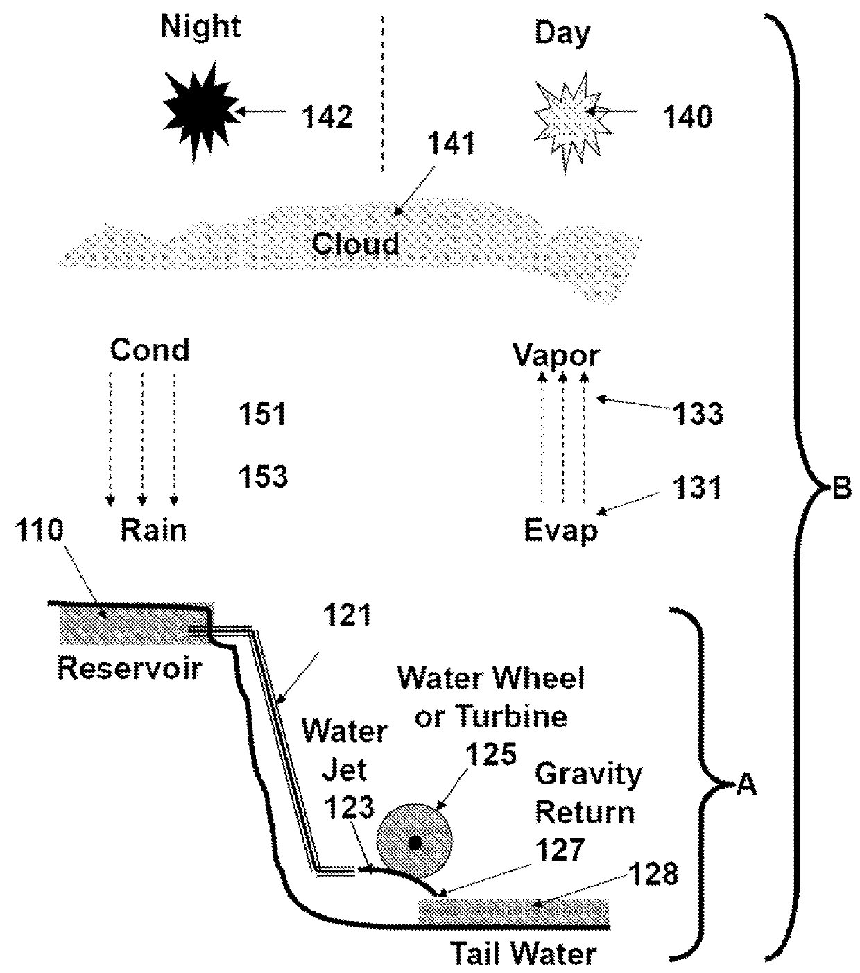
[0017]Water has a density of 700 times that of our atmosphere (wind) and seems to be the technology to zero in on for an efficient renewable energy source. The goal is to try to recreate the earth's Water Cycle Eco Support system (see FIG. 1) in a portable containment system, and put a “water fall” (hydroelectric power plant) in every house, business, auto, train, and boat. This technology, when put into mass production throughout the world, will have global disruptive, but positive impact, on changing existing trillion dollar roadmaps toward moving the world's population to a distributed energy system that will significantly reduce our dependency on fossil fuels in record time.

[0018]This invention will dramatically change the world's energy roadmap, initially suppressing the need for further development of water, wind, and solar alternative present day green renewable energy solutions, and over a much longer period of time will allow continental electrical distribution grids as we ...


PUM


Abstract

An Artificial Gravity Fueled Fluid Dynamic Day Energy Generator/Motor that initially uses external power to spin a partially submerged low drag fluid distributor rotor that uses centrifugal force to cause fluid to flow from the center of rotation, through a plurality of Euler contoured penstocks, in a true radial direction through a high “g” artificial gravity field, which dramatically increases the fluid's kinetic energy and releases available power, before it is guided out tangentially from the distributor via a plurality of nozzles symmetrically located at a small height just above the reservoir surface (near zero lift). As the frequency of the rotor is increased linearly the fuel Artificial Gravity increases exponentially, as does the fluid dynamic available power Pa. Turbine runners on the rotor assembly capture the available power, and a positive feedback mechanical transmission couples the captured rotational power to the I/O shaft in its initialized direction.

Description

TECHNICAL FIELD OF THE INVENTION[0001]The present invention relates generally to energy generation, hydro-mechanical power generation, and distributed green reusable energy.BACKGROUND OF INVENTION[0002]The global economy relies on a continuous, supply of coal, oil, and natural gas, and the refinement processes, necessary to produce power for virtually every power assisted device in the modern world. With the expanding growth in industrialization in new regions of the world, (China, OPEC nations, etc.) these high energy combustible fossil fuels are increasingly in demand at alarming rates causing supply and demand record high prices in highly volatile markets.[0003]The current trend in many nations is to reduce their dependency on fossil fuels with alternative energy technologies i.e., corn-base ethanol, hydrogen based fuels, etc. and to revive the old reusable, pollution free water, wind, and solar natural energy base technologies. All of these technologies have significant drawback...

Claims


Application Information

Patent Timeline
Patent Type & Authority Applications(United States)
IPC IPC(8): F03B17/06
CPCF03B17/061F03B3/08Y02E10/20
Inventor PRILL, ROBERT, S.
Owner PRILL ROBERT S
Why Eureka
Try Eureka