Vibration isolator

a technology of vibration isolator and isolator, which is applied in the direction of machine supports, shock absorbers, jet propulsion mountings, etc., can solve the problems of reducing design freedom and increasing manufacturing costs, and achieves the reduction of vibration-proof characteristics, increased manufacturing costs, and reduced design freedom

Active Publication Date: 2016-02-25
PROSPIRA CORP
View PDF16 Cites 26 Cited by
  • Summary
  • Abstract
  • Description
  • Claims
  • Application Information

AI Technical Summary

Benefits of technology

[0008]However, in the existing vibration isolator, there is a problem in that a manufacturing cost is increased because the valve body is provided to make a structure complicated, and because tuning of the valve body is also required. In addition, a degree of freedom of design is reduced due to the provision of the valve body. As a result, a vibration-proof characteristic may also be reduced.

Problems solved by technology

However, in the existing vibration isolator, there is a problem in that a manufacturing cost is increased because the valve body is provided to make a structure complicated, and because tuning of the valve body is also required.
In addition, a degree of freedom of design is reduced due to the provision of the valve body.

Method used


Image

  • Vibration isolator
  • Vibration isolator
  • Vibration isolator

Examples


Embodiment Construction

[0020]Hereinafter, an embodiment of a vibration isolator according to the present invention will be described based on the drawings.

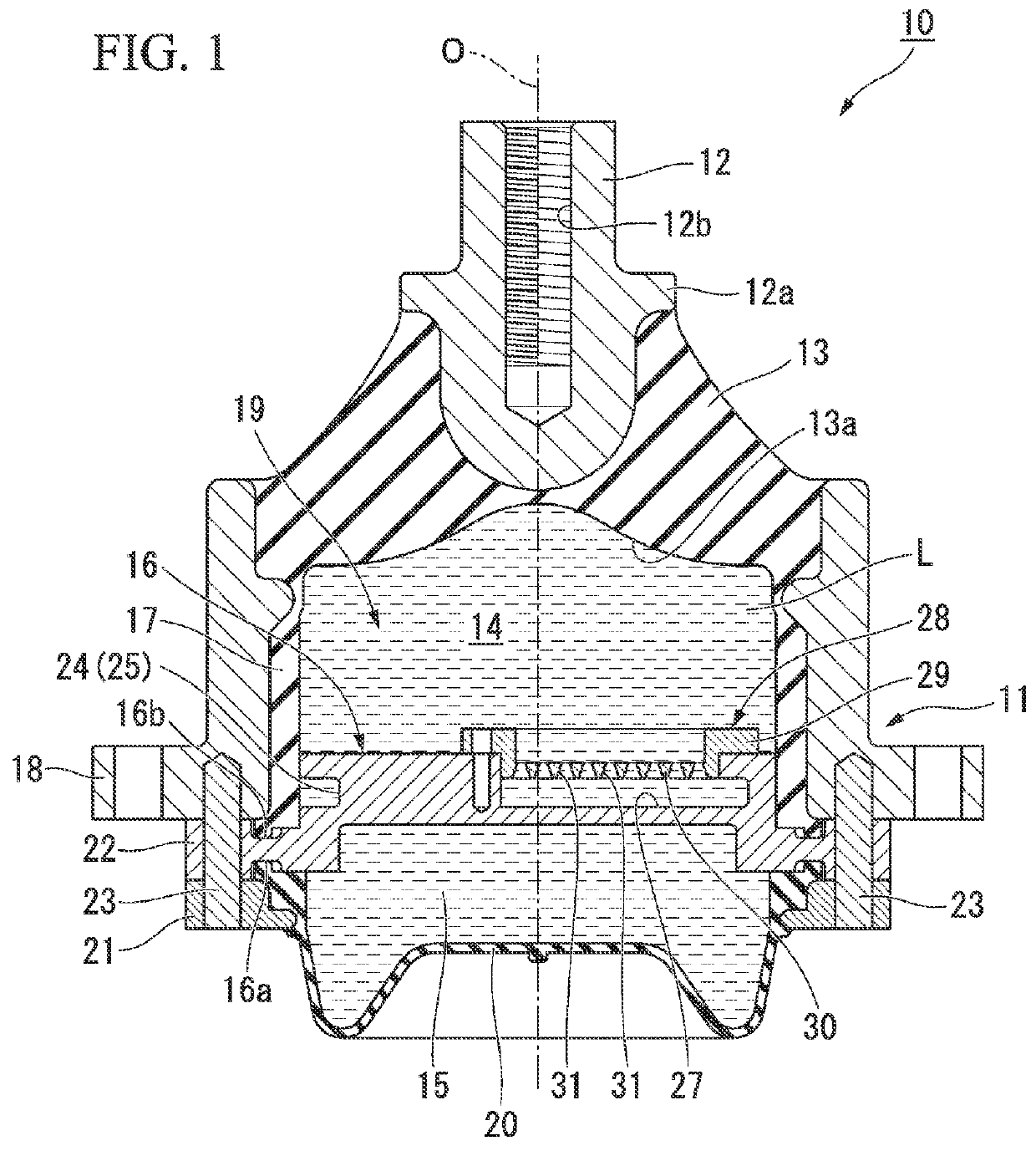
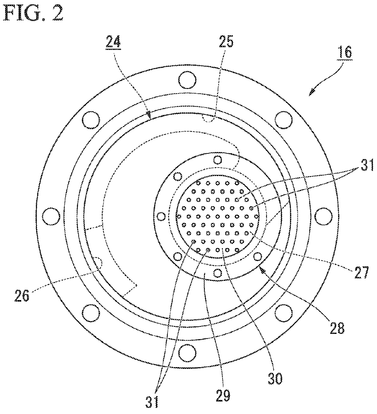
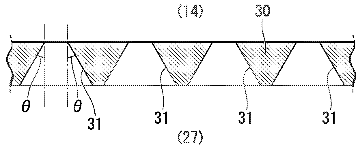
[0021]FIG. 1 is a longitudinal sectional view of a vibration isolator 10 taken along an axis O in the present embodiment. FIG. 2 is a top view of a partition member. FIG. 3 is a longitudinal sectional view of an essential part in a porous plate showing fine pores.

[0022]Note that a symbol O shown in FIG. 1 indicates a central axis of the vibration isolator 10, and is hereinafter referred to simply as “axis O.” Also, a direction parallel to the axis O is referred to as an “axial direction,” and a direction around the axis O is referred to as a “circumferential direction.”

[0023]As shown in FIG. 1, the vibration isolator 10 is equipped with a first mounting member 11 that is connected to one of a vibration generator and a vibration absorber and has a tube shape, a second mounting member 12 that is connected to the other of the vibration generator and the vi...


PUM


Abstract

A vibration isolator (10) is a liquid-enclosed vibration isolator and includes: a tubular first mounting member (11) connected to one of a vibration generator and a vibration absorber, and a second mounting member (12) connected to the other; an elastic body (13) elastically connecting the mounting members; and a partition member (16) partitioning a liquid chamber (19) in the first mounting member (11) within which a liquid (L) is enclosed into a primary liquid chamber (14) that uses the elastic body (13) as a part of a wall surface thereof and a secondary liquid chamber (15), wherein the partition member (16) is formed with a restriction passage (24) communicating the primary and secondary liquid chambers (14, 15) with each other, and a porous body (28) having numerous pores (31), which are disposed in parallel so as to communicate a side of the primary liquid chamber (14) and a side of the secondary liquid chamber (15) with each other, is arranged in the restriction passage (24).

Description

BACKGROUND OF THE INVENTION[0001]1. Field of the Invention[0002]The present invention relates to a vibration isolator that is applied to, for instance, a motor vehicle or an industrial machine so as to absorb and attenuate vibrations of a vibration generator such as an engine.[0003]Priority is claimed on Japanese Patent Application No. 2014-167273, filed Aug. 20, 2014, the content of which is incorporated herein by reference.[0004]2. Description of Related Art[0005]Conventionally, such a vibration isolator has been known as being made up of a tubular first mounting member that is connected to one of a vibration generator and a vibration absorber, a second mounting member that is connected to the other, an elastic body that connects these mounting members, and a partition member that partitions a liquid chamber in the first mounting member within which a liquid is enclosed into a primary liquid chamber and a secondary liquid chamber. The partition member is formed with a restriction ...

Claims


Application Information

Patent Timeline
Patent Type & Authority Applications(United States)
IPC IPC(8): F16F13/10B60K5/12F16F13/08
CPCF16F13/107B60K5/1208F16F13/08
Inventor UEKI, AKIRANAGASAWA, MASAKAZUONO, SHUHEINAGASHIMA, YASUYUKI
Owner PROSPIRA CORP
Why Eureka
Try Eureka