Lubricating Device for Transmission

a lubricating device and transmission technology, applied in the direction of gearing details, gear lubrication/cooling, belt/chain/gearing, etc., can solve the problems of difficult oil flow in the oil hole, high rotational speed of the oil catcher, and increased axial dimension of the transmission, so as to reduce the number of parts of the lubricating device for transmission, reduce the size, weight and manufacturing cost of the automatic transmission

Inactive Publication Date: 2016-02-25
AISIN AI CO LTD
View PDF0 Cites 9 Cited by
  • Summary
  • Abstract
  • Description
  • Claims
  • Application Information

AI Technical Summary

Benefits of technology

[0007]Thus, as the cylindrical rotational member that delivers the oil is provided between the bearings for supporting the rotational shaft, when the lubricating device for transmission is provided to the transmission, the axial length of the transmission does not become long, and it is possible to decrease the size of the transmission in the axial direction. Also, as the lubricating device for transmission is a screw pump that delivers the oil by rotating the cylindrical rotational member formed with oil delivery groove on the outer peripheral surface thereof, regardless of the rotational speed of the rotational shaft to which the cylindrical rotational member is fixed, the oil can be delivered in a stable manner.
[0008]Also, the outer peripheral surface of the cylindrical rotational member is covered by the rotational member housing portion of the transmission housing that rotatably supports the rotational shaft. Thus, the transmission housing is formed with the space in which the cylindrical rotational member is accommodated, and is used as a casing of the lubricating device for transmission. Therefore, it is possible to reduce the number of parts constituting the lubricating device for transmission. Accordingly, it is possible to reduce the size, weight, and manufacturing cost of the automatic transmission.

Problems solved by technology

Thus there is a problem that the axial dimension of the transmission is increased.
Also, when the rotational speed of the output shaft becomes high, the rotational speed of the oil catcher becomes high, the oil that is rotated by the catcher is moved outward by centrifugal force, and it becomes difficult for the oil to flow in the oil hole.
As a result, there is a problem that delivery amount of the oil by the lubricating device for transmission becomes small.

Method used


Image

  • Lubricating Device for Transmission
  • Lubricating Device for Transmission

Examples


Embodiment Construction

Structure of the Transmission

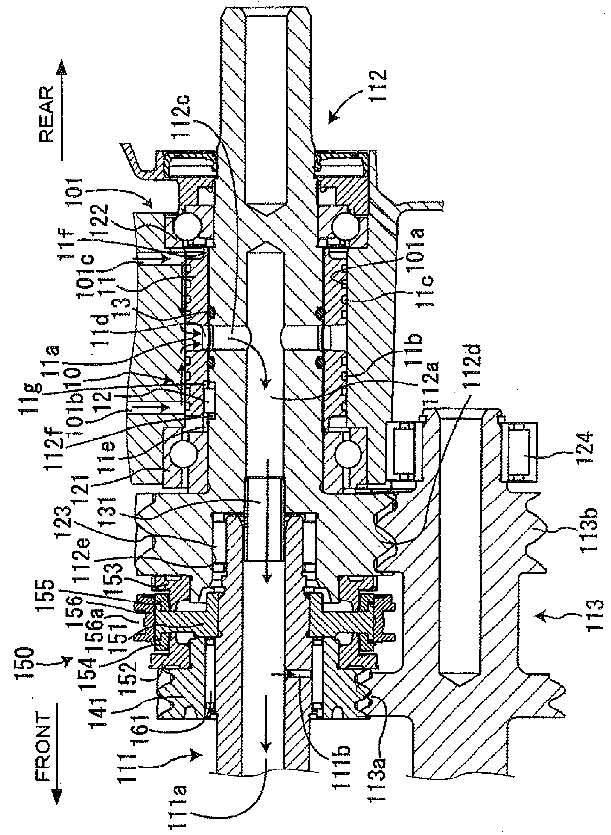
[0012]A structure of a transmission 100 to which a lubricating device 10 for transmission in accordance with an embodiment of the present invention is attached will be described below with reference to FIG. 1. As shown in FIG. 1, a transmission 100 includes a transmission housing 101, an input shaft 111, an output shaft 112, a counter shaft 113, a first bearing 121, a second bearing 122, a third bearing 123, a fourth bearing 124, a connecting member 131, a plurality of drive gears 141, a plurality of synchronizer mechanisms 150, a lubricating device 10 for transmission 100. In FIG. 1, the left side of the sheet is the front side of the transmission 100 and the respective components constituting the transmission 100, and the right side of the sheet is the rear side of the transmission 100 and the respective components constituting the transmission 100.

[0013]The output shaft 112 is rotatably supported by the first bearing 121 and the second bearing 122 att...


PUM


Abstract

A lubricating device for transmission includes a rotational shaft provided in a transmission housing, bearings attached to the transmission housing for supporting the rotational shaft, a cylindrical rotational member fixed to the rotational shaft between the bearings at an outer peripheral of said rotational shaft, at least one oil delivery groove which is spirally formed on an outer peripheral surface of the cylindrical rotational member, the outer peripheral surface of the cylindrical rotational member being covered by a rotational member housing portion of the transmission housing.

Description

CROSS REFERENCE TO RELATED APPLICATIONS[0001]This application is based on and claims priority under 35 U.S.C. §119 to Japanese Patent Application 2014-169058, filed on Aug. 22, 2014, the entire contents of which is incorporated herein reference.FIELD OF THE INVENTION[0002]The present invention relates to a lubricating device for supplying oil to a member of a bearing or the like of a transmission.BACKGROUND[0003]Conventionally, as disclosed in JP2003-42273 A, the lubricating device for transmission comprises a blade-shaped oil catcher (lubricating oil guiding member) fixed to an output shaft of transmission and a housing for covering the output shaft and the oil catcher. With the rotation of the output shaft, the oil catcher is rotated, and oil also rotates within the housing, and accordingly the oil flows into an oil hole formed in the output shaft. By this circulation of oil, oil is delivered to a member of a bearing or the like of the transmission.[0004]However, because the lubri...

Claims


Application Information

Patent Timeline
Patent Type & Authority Applications(United States)
IPC IPC(8): F16H57/00F16H57/04
CPCF16H57/043F16H57/0471F16H57/0018F16H57/0428F16H57/0494
Inventor ICHIKAWA, MASAYAOSAWA, HIDEYA
Owner AISIN AI CO LTD
Why Eureka
Try Eureka