Check patentability & draft patents in minutes with Patsnap Eureka AI!

Advanced tactical line replaceable unit alignment system

a technology of replacing units and alignment systems, applied in navigation instruments, instruments, manufacturing tools, etc., can solve problems such as the interpretation of results and measurement accuracy variations, the need for new tools, and the inability to standardize techniques and procedures

Active Publication Date: 2016-02-25
BAE SYST INFORMATION & ELECTRONICS SYST INTERGRATION INC
View PDF2 Cites 4 Cited by
  • Summary
  • Abstract
  • Description
  • Claims
  • Application Information

AI Technical Summary

Benefits of technology

The invention provides a system and method for mounting a new line replaceable unit (LRU) to a piece of equipment. The system includes a handheld inertial measurement unit (IMU) that can be manipulated by a single person, a computer logic, and a mounting interface. The handheld IMU is positioned adjacent the mounting interface to determine position data with respect to the LRU mount and the piece of equipment. The computer logic calculates a positional error value based on the position data, indicating whether corrections need to be made to the LRU mount before mounting it or if it can be mounted without corrections. The method includes removing the old device from the device mount, attaching a new device mounting interface, measuring position data, transmitting the data to the computer logic, determining the position error value, compensating for the position error value, and installing the new device. The technical effects include simplifying the process of mounting LRUs to equipment and reducing the likelihood of positional errors.

Problems solved by technology

This has led to non-standardized techniques and procedures, resulting in differing interpretations of results and variations in measurement accuracy.
New problems surface from the recent concept of operations updates which require precise / consistent alignment measurements to be made in-theatre.
Given the complexity, variation in accuracy, measurement standardization difficulties, and time required to calculate final results, a new tool was required.

Method used


Image

  • Advanced tactical line replaceable unit alignment system
  • Advanced tactical line replaceable unit alignment system
  • Advanced tactical line replaceable unit alignment system

Examples


Embodiment Construction

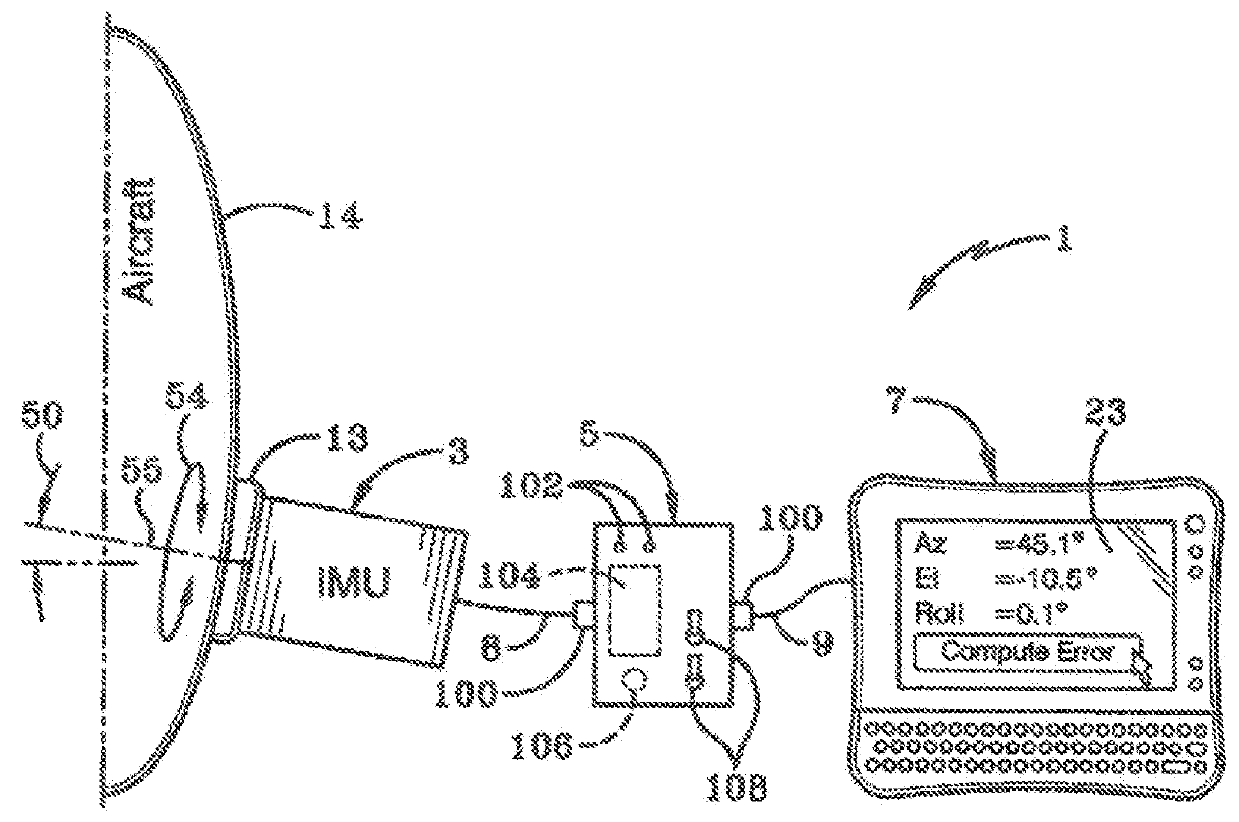
[0021]The invention typically comprises an Advanced Tactical LRU Alignment System (ATLAS) that uses an inertial measurement unit (IMU) technology. It was designed around an end user who requires minimal knowledge of the alignment process and features an easy-to-follow graphical user interface (GUI), embedded mathematics, built-in standardization of measurement procedures, and automatic generation of alignment / alignment verification results. It allows for precision measurements to be performed quickly and easily. The system has been designed to facilitate LRU alignment measurements for threat warning and countermeasure systems as well as general alignment measurements for any other equipment.

[0022]FIG. 1A illustrates the sample embodiment of a system 1 used for the accurate alignment of LRUs. The system includes a handheld IMU 3, an interface box 5 and a laptop computer 7. When in use, these components are connected together with cables 8, 9. In some configurations, interface box 5 m...


PUM

PropertyMeasurementUnit
total angleaaaaaaaaaa
single angle accuracyaaaaaaaaaa

Abstract

A system and method for mounting a device to a piece of equipment is presented, and may include a handheld inertial measurement unit (IMU), a computer logic and a mounting interface. The piece of equipment may have a line replaceable unit (LRU) mount that allows a new LRU to be mounted thereon. The mounting interface may be mounted to a LRU mount. The handheld IMU may determine position data with respect to the LRU mount and the piece of equipment. The computer logic may be configured to calculate a positional error value based on the position data to indicate to a user whether corrections need to be made regarding how the new LRU is mounted to the LRU mount before the new LRU is mounted to the LRU mount or whether the new LRU can be mounted to the LRU mount without any corrections.

Description

CROSS REFERENCE TO RELATED APPLICATION[0001]This application is a divisional application of Ser. No. 13 / 940,002 filed Jul. 11, 2013 and claims priority from U.S. Provisional Application Ser. No. 61 / 670,323 filed Jul. 11, 2012; the disclosure of which is incorporated herein by reference.BACKGROUND OF THE INVENTION[0002]1. Field of Invention[0003]The current invention relates generally to apparatus, systems and methods for mounting devices to equipment. More particularly, the apparatus, systems and methods relate to mounting devices to equipment at a precise orientation. Specifically, the apparatus, systems and methods provide for generating positioning information automatically to aid a user in mounting a device to a piece of equipment.[0004]2. Description of Related Art[0005]During the system integration process, precision alignment of Line Replaceable Units (LRUs) to each other and the host platform is often required. The current methods of precision alignment rely on tools that we...

Claims


Application Information

Patent Timeline
Patent Type & Authority Applications(United States)
IPC IPC(8): G01D5/02B64D47/00
CPCB64D47/00G01D5/02G01C25/005Y10T29/49718Y10T29/49721Y10T29/4973Y10T29/49771Y10T29/49826G01C21/166G01C21/183B23P19/04G01C1/00G01C17/38G01C21/20G01C21/06
Inventor RAMSEY, ERIC R.BELL, BRADLEY J.FORBES, TYLER D.
Owner BAE SYST INFORMATION & ELECTRONICS SYST INTERGRATION INC
Features
  • R&D
  • Intellectual Property
  • Life Sciences
  • Materials
  • Tech Scout
  • Unparalleled Data Quality
  • Higher Quality Content
  • 60% Fewer Hallucinations
Learn More