
Reduction of positional errors in a four point probe resistance measurement

a technology of resistance measurement and positional error reduction, which is applied in the direction of resistance/reactance/impedence, instruments, measurement devices, etc., can solve the problems of resistivity measurement errors, and achieve the effect of reducing the measurement errors resulting from the positioning of the prob

Active Publication Date: 2005-09-13
IBM CORP
View PDF3 Cites 105 Cited by
  • Summary
  • Abstract
  • Description
  • Claims
  • Application Information

AI Technical Summary

Benefits of technology

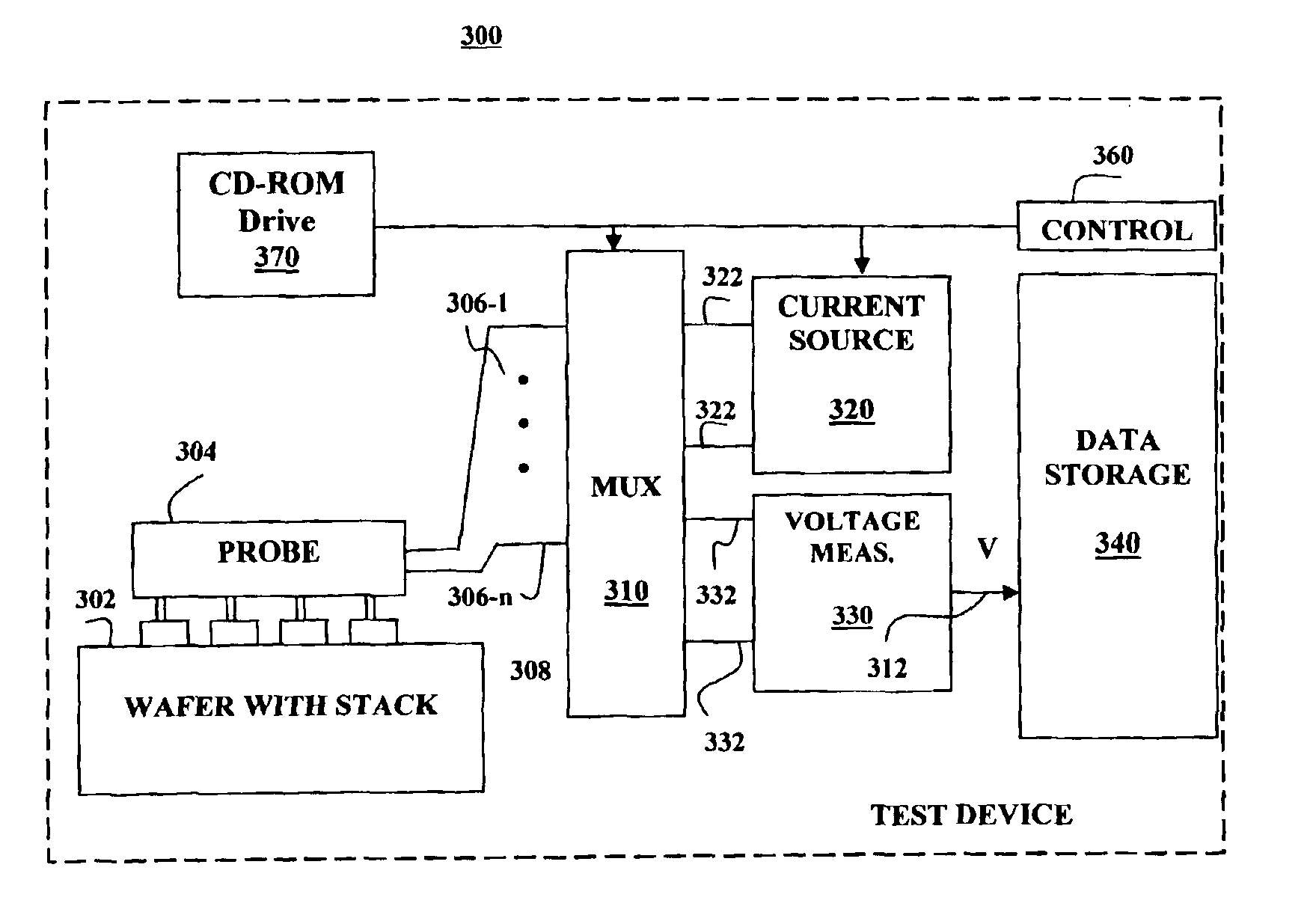
[0011]A system for measuring resistance per square on a surface of a material comprises a probe comprising first, second, third and fourth electrodes; a current source for inducing a current from a selected electrode to a second selected electrode; a voltage meter for measuring a voltage difference between a pair of selected electrodes; and a multiplexer comprising a plurality of output lines connected to the probe and a plurality of input connections, at least two of which are connected to the current source and at least another two of which are connected to the voltage meter; and a controller coupled to the multiplexer. The controller comprises logic for making a first measurement using a first set of probe electrodes for inducing a current and a second set of probe electrodes for measuring the voltage difference when the current is induced; making a second measurement each using a set of probe electrodes different from the first set for inducing a current and a set of probe electrodes different from the second set for measuring the voltage difference when the current is induced; and using a known relationship among: the currents induced; the voltages measured; the nominal probe positions; and the resistance per square to determine the resistance per square such that measurement errors resulting from positioning of the probes are reduced.

Problems solved by technology

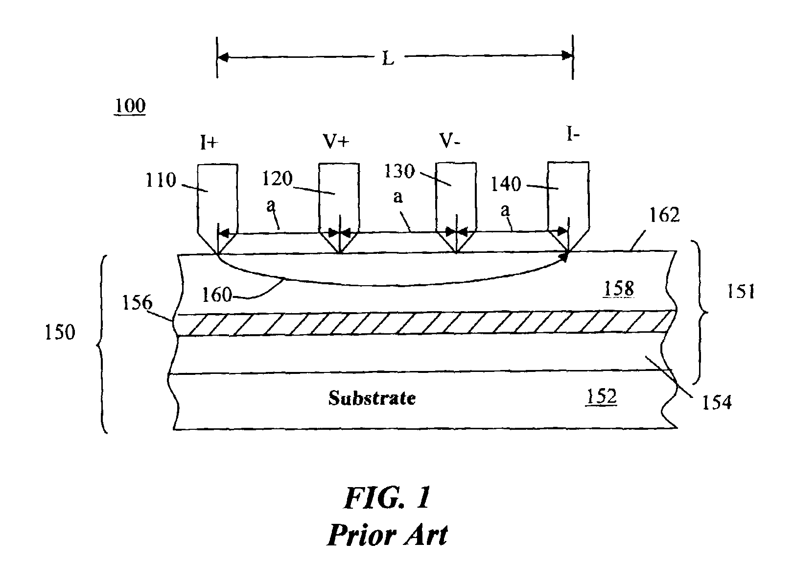
The method for measuring resistance or resistivity of wafer materials used by the apparatus of FIG. 1 works well for many purposes; however errors can occur in the resistivity measurements caused by the position of the probe points on the subject wafer or sheet.

Method used


Image

  • Reduction of positional errors in a four point probe resistance measurement
  • Reduction of positional errors in a four point probe resistance measurement
  • Reduction of positional errors in a four point probe resistance measurement

Examples


Embodiment Construction

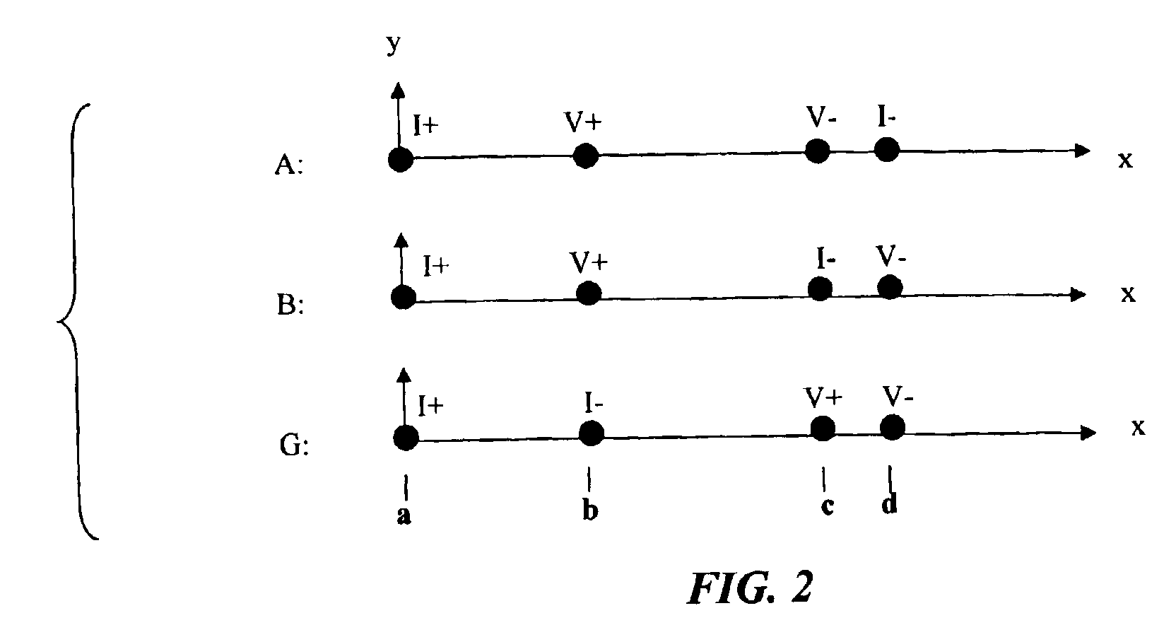
[0019]According to an embodiment of the invention, a method for measuring a resistance per square, R□, of a material (e.g., a semiconductor wafer) uses a four-point probe such as the one depicted in FIG. 1 for making a plurality of resistance measurements we shall call A, B, and G to eliminate errors due to the positions of the probe points. The method implements an algorithm comprising making two or more measurements, each using a different combination of probe electrodes and then using a known relationship to determine a resistance per square that eliminates measurement errors resulting from positioning of the probes.

[0020]The resistivity measurement commences by bringing the contact points (such as those shown in FIG. 1 and identified with numerals 110-140) into contact with a surface of a wafer or sheet material 150 to be measured. FIG. 2 shows a series of resistance measurements A, B, and G made on a set of four points a, b, c, and d that are located in the interior of the mate...


PUM


Abstract

A system and method for measuring a resistance or a resistance per square, Rsq, of a material having a surface using a multi-point probe including four or more collinear contact points placed in the interior of the sample, the method including: making a first measurement using a first set of probe electrodes for inducing a current and a second set of probe electrodes for measuring the voltage difference when the current is induced; making a second measurement using a set of probe electrodes different from the first set for inducing a current and a set of probe electrodes different from the second set for measuring the voltage difference when the current is induced; and using a known relationship among the currents induced, the voltages measured, the nominal probe positions and the resistance per square to determine the resistance per square such that measurement errors resulting from positioning of the probes are reduced.

Description

FIELD OF THE INVENTION[0001]The invention disclosed broadly relates to the field of resistance measurement probes and more specifically to four point probes for resistance measurements in semiconductor wafers.BACKGROUND OF THE INVENTION[0002]Probes for measuring resistivity in sheets and wafers are known in the art. One example of such probes is the four-point probe as shown in FIG. 1. The purpose of a 4-point probe is to measure the resistivity of a semiconductor material. It can measure either bulk or thin film specimens.[0003]Referring to FIG. 1, there is shown a four-point resistivity probe 100. The probe 100 comprises four electrodes 110, 120, 130, and 140 for probing a wafer 150. In this example consider each of the electrodes to be equally spaced. The probe is placed in the interior of the sample, and the probes are collinear. Generally, the probe 100 works by applying a known level of current, I, between electrodes 110 and 140 via the wafer 150. Then the voltage, V, between ...

Claims


Application Information

Patent Timeline
IPC IPC(8): G01R27/14G01R31/26
CPCG01R27/14G01R31/2648
Inventor WORLEDGE, DANIEL
Owner IBM CORP
Learn More