Multilayer ceramic structure, manufacturing method therefor and piezoelectric actuator
a ceramic structure and manufacturing method technology, applied in the direction of piezoelectric/electrostrictive transducers, generators/motors, transducer types, etc., can solve the problems of insufficient measurement accuracy, complicated handling, adverse effects, etc., to facilitate poling and inspection, and easy to be subjected to poling and inspection of electrical characteristics
- Summary
- Abstract
- Description
- Claims
- Application Information
AI Technical Summary
Benefits of technology
Problems solved by technology
Method used
Image

Examples
first embodiment
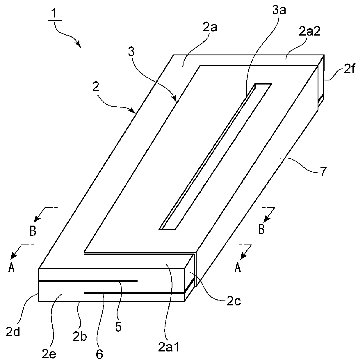
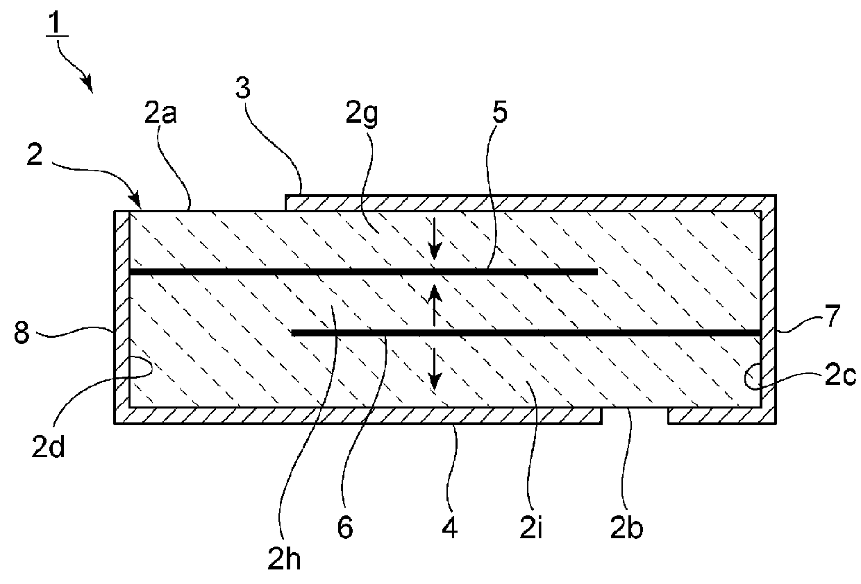
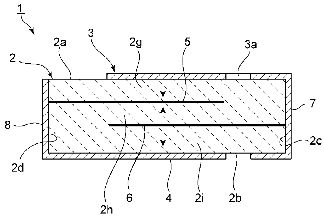
[0049]FIG. 1 is a perspective view of a multilayer ceramic structure according to the present invention. FIGS. 2 and 3 are sectional views of portions along line A-A and line B-B in FIG. 1, respectively.
[0050]A multilayer ceramic structure 1 includes a multilayer ceramic body 2. The multilayer ceramic body 2 has a rectangular parallelepiped shape. More specifically, the multilayer ceramic body 2 has an upper surface 2a, a lower surface 2b, first and second side surfaces 2c and 2d that oppose each other, and first and second end surfaces 2e and 2f that oppose each other. A direction that connects the first end surface 2e and the second end surface 2f is a first direction. That is, the upper surface 2a, the lower surface 2b and the first and second side surfaces 2c and 2d extend in the first direction.
[0051]In addition, a direction that connects the first side surface 2c and the second side surface 2d is a second direction that is orthogonal to the first direction.
[0052]The multilayer...
second embodiment
[0084]FIG. 6 is a perspective view of a multilayer ceramic structure according to the present invention. In a multilayer ceramic structure 21, a slit 3a of an upper surface opposing electrode 3 is not closed at an end portion of the upper surface opposing electrode 3 on a second end surface 2f side and is open toward the second end surface 2f side. Thus, the slit 3a may be open toward the second end surface 2f side. Alternatively, the slit 3a may be open toward a first end surface 2e side rather than the second end surface 2f side. However, it is necessary that an electrical connection be made to portions on both sides of the slit 3a of the upper surface opposing electrode 3 in order to perform poling.
[0085]The rest of the configuration of the multilayer ceramic structure 21 is the same as that of the multilayer ceramic structure 1 and therefore the same effect as in the first embodiment is exhibited.
[0086]FIG. 7 is a perspective view of a multilayer ceramic structure according to a...
fourth embodiment
[0096]FIG. 13 is a perspective view of a multilayer ceramic structure according to the present invention.
[0097]A multilayer ceramic structure 41 includes a rectangular-parallelepiped-shaped multilayer ceramic body 42. The multilayer ceramic body 42 has an upper surface 42a, a lower surface 42b, first and second side surfaces 42c and 42d, and first and second end surfaces 42e and 42f.
[0098]In addition, in the multilayer ceramic body 42, ceramic layer 42g and 42h, which are composed of a piezoelectric ceramic, are stacked one of top of the other.
[0099]An upper surface opposing electrode 43 is formed on the upper surface 42a. The upper surface opposing electrode 43 is different from that of the first embodiment and does not have a slit. The upper surface opposing electrode 43 is led out to an edge formed by the upper surface 42a and the first side surface 42c. The upper surface opposing electrode 43 is electrically connected to a first side surface electrode 47. The first side surface...
PUM
 Abstract
Description
Claims
Application Information
 - R&D
- Intellectual Property
- Life Sciences
- Materials
- Tech Scout
- Unparalleled Data Quality
- Higher Quality Content
- 60% Fewer Hallucinations
Browse by: Latest US Patents, China's latest patents, Technical Efficacy Thesaurus, Application Domain, Technology Topic, Popular Technical Reports.
© 2025 PatSnap. All rights reserved.Legal|Privacy policy|Modern Slavery Act Transparency Statement|Sitemap|About US| Contact US: help@patsnap.com