Extension device for the neck of a container formed in a machine for forming containers from preforms

a technology of extension device and container, which is applied in the direction of transportation and packaging, other domestic articles, packaging goods types, etc., can solve the problems of reducing the throughput of the machine, spilling the liquid contained in the container, and poor quality of the container

Active Publication Date: 2016-03-03
DISCMA
View PDF1 Cites 15 Cited by
  • Summary
  • Abstract
  • Description
  • Claims
  • Application Information

AI Technical Summary

Benefits of technology

[0017]The extension device attached to the neck of the preforms is able to protect the neck against deformation during the injection of the liquid at high pressure and during the forming and filling of the container. Furthermore, the extension part of the extension device increases the height of the neck of the container, thereby offering an extra space for the liquid contained in the formed containers, which reduces the risks of spilling the content of the containers.
[0041]Such a conical shape of the inner cylindrical opening prevents liquid from being trapped in the extension device and ensures that any liquid present in the extension part will flow from said central bore towards the inner opening of the neck.

Problems solved by technology

However, the high pressure of the injection can deform the neck of the preforms, which then forms a container of poor quality, which has to be rejected.
The number of unsatisfactory containers due to neck deformation reduces the throughput of the machine.
This centrifugal force, and more generally transporting the containers at high speed, can lead to spilling the liquid contained in the containers.
However, the mold holder is hard to clean due to its complicated structure, and cleaning the mold holder implies stopping the rotation of the wheel and therefore reduces the throughput of the forming station.
An insufficient cleaning of the molds and mold holders can lead to cross-contamination in the hydraulic forming method.
However, such a machine has a complicated structure and can lead to difficulties for placing the preforms in the molds and for retrieving the formed and filled containers from the molds.
However, this document does not mention the problem of preventing the spilling of the liquid once the container has been filled and does not disclose a solution to this problem.
US-2012 / 0187133 also does not disclose this problem and an appropriate solution to it.

Method used


Image

  • Extension device for the neck of a container formed in a machine for forming containers from preforms
  • Extension device for the neck of a container formed in a machine for forming containers from preforms
  • Extension device for the neck of a container formed in a machine for forming containers from preforms

Examples


first embodiment

[0062]According to the machine, successive preforms 2 are introduced in the machine shown in FIG. 8 and are introduced in an extension attaching station 13 for attaching an anti-spilling device to neck 6 of each preform 2. The anti-spilling device is for example made of a hydrophobic material or is coated with such a hydrophobic material for guarantying the return of the liquid inside the container 1 during the forming and filling of said container.

[0063]According to the first embodiment, the anti-spilling device is intended to be attached to the preform such that the anti-spilling device is moved with the preform and with the formed container obtained after a forming and filling process has been performed on the preform and follows the path of the preform from the extension attaching station 13, to a extension detaching station or to a station for shaping the anti-spilling device into a cap, as will be described subsequently.

[0064]According to the first embodiment, the anti-spillin...

second embodiment

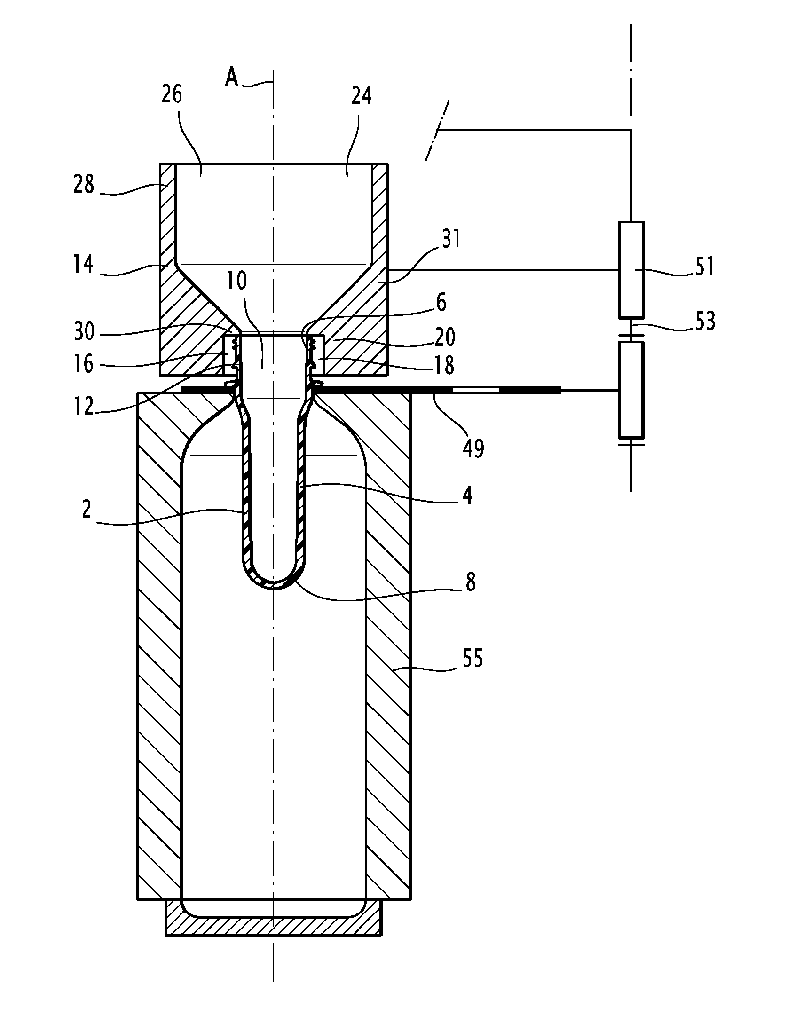
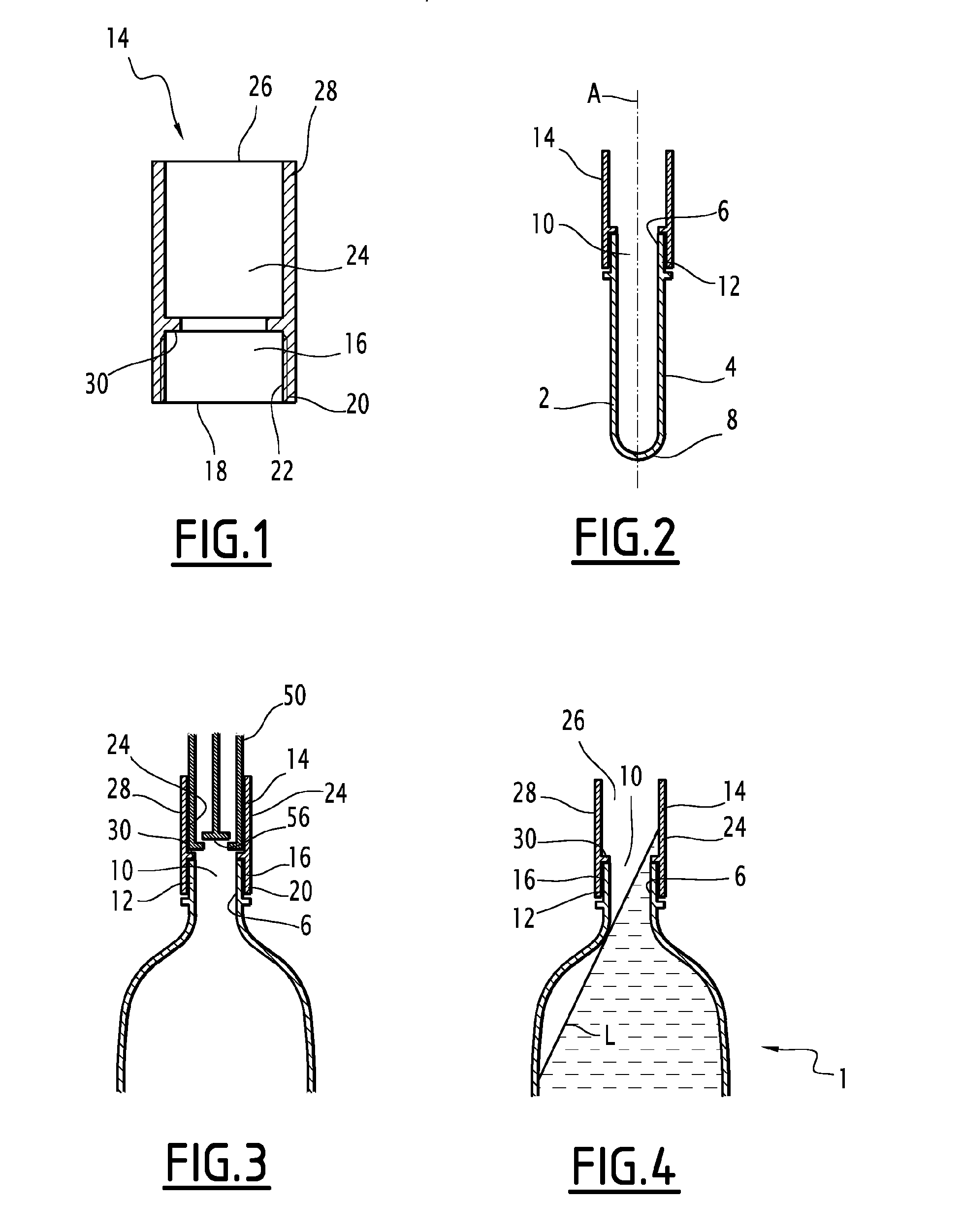
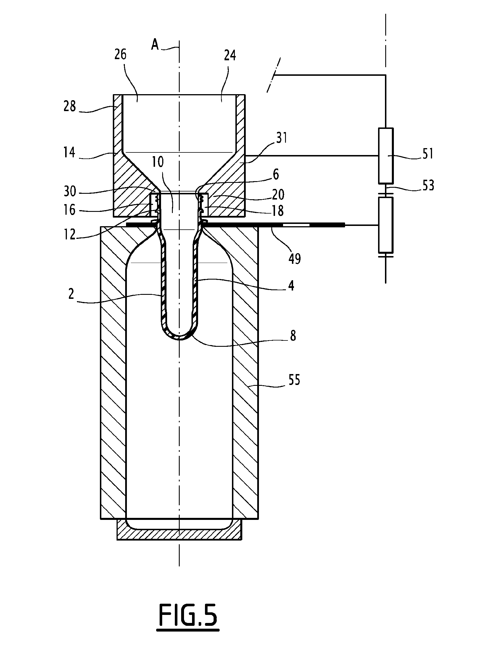
[0078] shown in FIGS. 5 to 7, the anti-spilling device is intended to be placed on the neck of a preform without being attached to it.

[0079]The extension attaching means are arranged to place the extension devices 14 on the neck 6 of the preforms, without attaching the extension devices on the necks 6. In this case, the diameter of the inner opening 18 of the connection part 16 is larger than the outer diameter of the neck 6 and the shoulder 30 resting on the end of the neck 6 of the preform 2 is arranged to form a seal between the inner volume of the extension part 24 and the space between the outer face of the neck 6 and the wall 20 of the connection part 16 of the extension device 14, thereby preventing any liquid from liquid in this space, when the liquid is in the inner volume of the extension part 24.

[0080]According to the second embodiment, each extension device 14 is attached to a neck holding part 49 arranged to hold a preform and the resulting formed container by its neck ...


PUM

PropertyMeasurementUnit
pressureaaaaaaaaaa
lengthaaaaaaaaaa
lengthaaaaaaaaaa

Abstract

A method for producing a container from a preform having a body and a neck defining an inner cylindrical opening. The method including the steps of placing the preform in a mold having a molding cavity, forming the container by injecting a forming fluid into the preform, and filling the container with a liquid. Prior to forming of the container, an extension device is attached to the neck of the preform. The extension device includes an extension part defining an inner opening extending in the continuity of the inner opening of the neck. The extension device remaining attached to the neck of the preform at least during the forming and the filling steps.

Description

CROSS-REFERENCE TO RELATED APPLICATIONS[0001]This application is the U.S. national phase of PCT Application No. PCT / EP2014 / 057163 filed on Apr. 9, 2014, and claims priority to EP13305463.5 filed on Apr. 9, 2013, the disclosures of which are incorporated in their entirety by reference herein.TECHNICAL FIELD OF THE INVENTION[0002]The present invention relates to method for producing a container from a preform by injecting a liquid inside successive preforms placed in successive molds.[0003]The invention also relates to a machine for producing containers from preforms and to an assembly comprising a preform or a container and an extension device for implementing such a method.[0004]The invention relates to the field, known as hydro forming, of forming containers from a preform using an incompressible liquid to deform the preform.[0005]In the application, “liquid” has a physical meaning. It designates any incompressible and able to flow medium. The liquid can have a low viscosity (like ...

Claims


Application Information

Patent Timeline
Patent Type & Authority Applications(United States)
IPC IPC(8): B29C49/46B65B3/02B65B3/10B65B7/28B65B51/22
CPCB65B3/022B29L2031/7158B29C49/06B29C2049/5862B29C2049/4664B65B7/285B65B51/22B29C2049/465B29C2049/224B29C49/46B65B7/2842B65B3/10B29K2101/12B29C2949/0715B29C2949/20B29C2949/3008
Inventor DIESNIS, DANIELPICOT, BENOIT
Owner DISCMA
Why Eureka
Try Eureka