Airbag device for motor vehicle

a technology for airbags and motor vehicles, which is applied in the direction of vehicular safety arrangements, vehicle components, pedestrian/occupant safety arrangements, etc. it can solve the problems of slow inflation and expansion speed of the airbag for front passenger seats, and the difficulty of gas efficient flow into, so as to reduce manufacturing costs, increase inflation and expansion speed of the center side airbag, and reduce the effect of gas capacity

Active Publication Date: 2016-03-03
NIHON PLAST CO LTD
View PDF3 Cites 27 Cited by
  • Summary
  • Abstract
  • Description
  • Claims
  • Application Information

AI Technical Summary

Benefits of technology

[0011]According to the aspect of the present invention, the communication portions are formed on the first airbag at the side face portion to which the second airbag is arranged, and includes: at least a first communication portion and a second communication portion; an intake hole formed in the second airbag adjacent to the first communication portion; and a communication passageway having a predetermined length, wherein the first communication portion is arranged so as to be proximal to the inflator at the side face portion of the airbag for front passenger seat than the other communication portion, the second communication portion is arranged so as to be proximal to an occupant side end than the other communication portion on the side face portion of the first airbag after inflated and expanded, the second communication portion and the second airbag are communicated directly, and the first communication portion and the second airbag are communicated via a communication passageway communicated with the first communication portion and the intake hole. In this manner, when the gas that is ejected from the inflator is flowed into the first airbag through the gas inflow hole, the first airbag inflates and expands in an early stage and the gas that is ejected in an

Problems solved by technology

However, the related art is directed to a structure in which the center side airbag is inflated by gas that is ejected from the inflator and subsequently the airbag for front passenger seat starts its inflation via the communication hole; and therefore, owing to

Method used


Image

  • Airbag device for motor vehicle
  • Airbag device for motor vehicle
  • Airbag device for motor vehicle

Examples


first embodiment

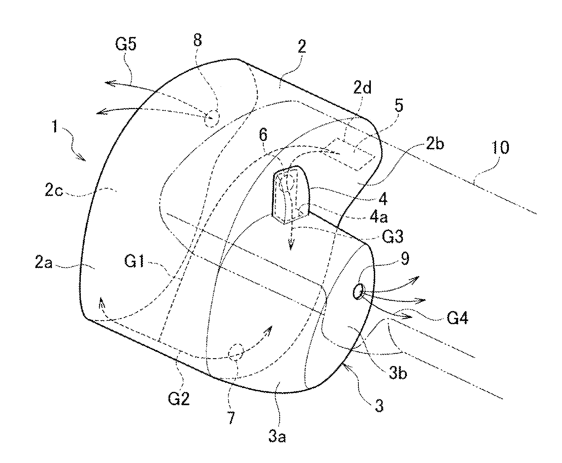
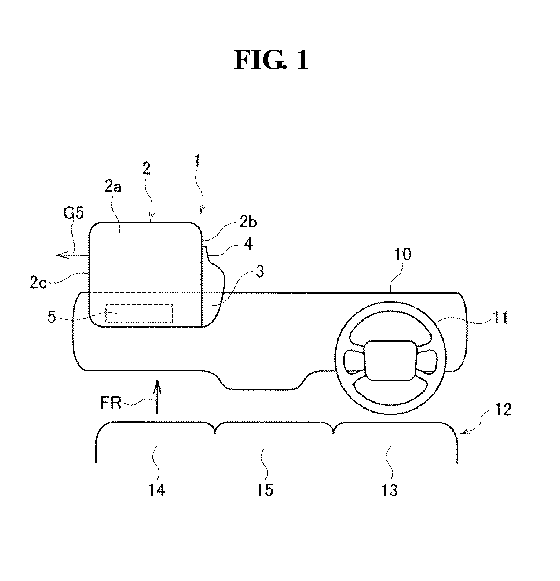
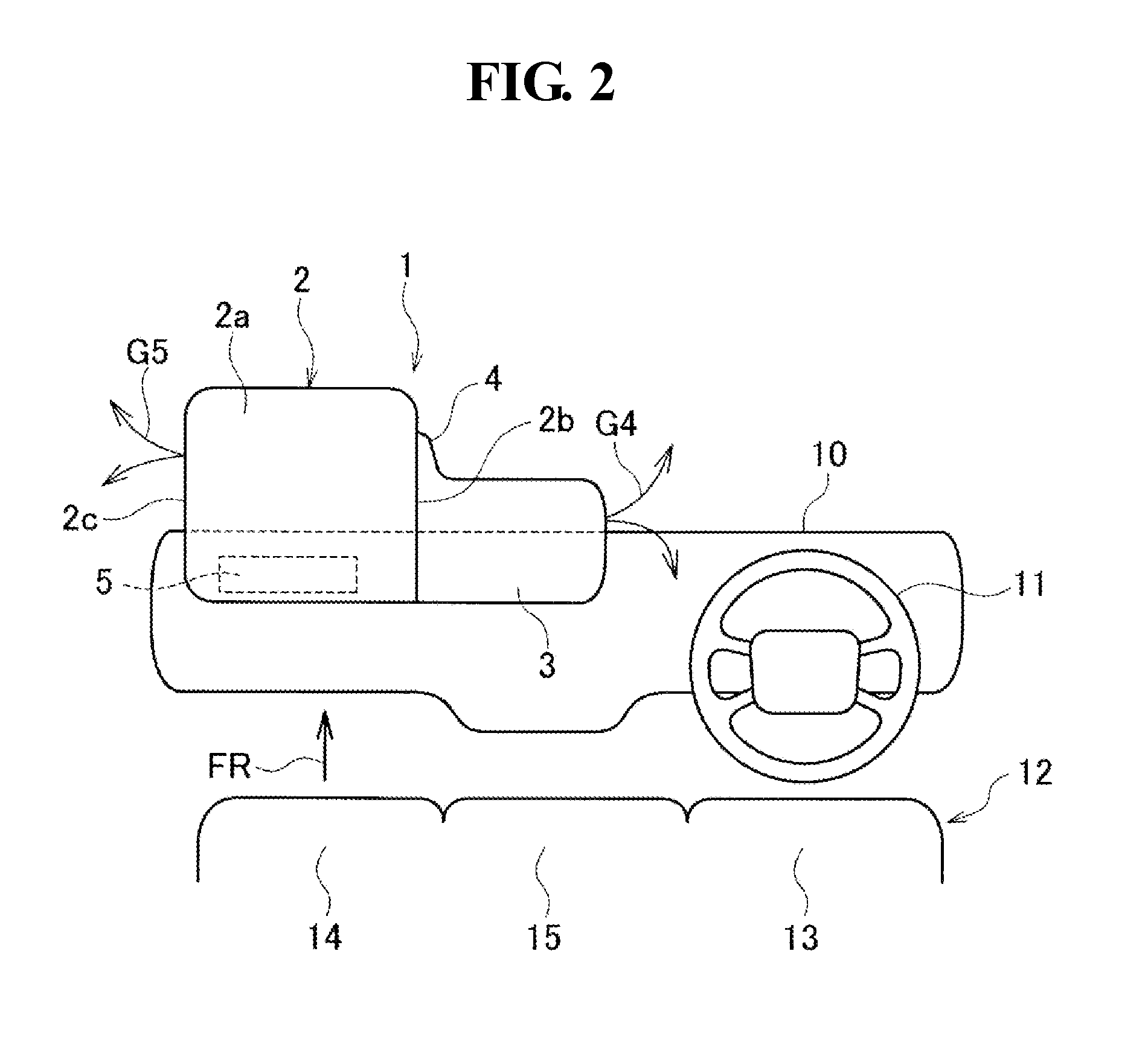
[0020]A structure according to a first embodiment of the present invention will be described with reference to FIG. 1 to FIG. 5. An airbag device 1 for motor vehicle, according to the first embodiment, is provided with: a sensor which detects rapid braking or the like at the time of a collision or any other event similar thereto (not shown); an inflator 5 which is arranged at a front side FR area of a front passenger seat 14 of an instrument panel 10 and which is capable of ejecting and supplying gas by way of a signal from the sensor; an airbag 2 (first airbag) for front passenger seat having a gas inflow hole 2d which is connected to the inflator 5 and into which gas G1 ejected from the inflator 5 can be flowed; and a center side airbag 3 (second airbag) which is arranged on a center a transverse side of the airbag 2 for front passenger seat, in other words, in the front side FR area of a center seat 15 arranged between the passenger seat 14 and a driver seat 13, a respective one ...


PUM


Abstract

An airbag device for motor vehicle, includes: an inflator arranged in an instrument panel in front of a front passenger seat and is capable of ejecting gas; a first airbag connected to the inflator at a base end side thereof and has a gas inflow hole through which gas can be flowed, the first airbag being for the front passenger seat; and a second airbag arranged on the first airbag at a side face portion close to a center in the vehicle width direction, the second airbag being adapted to communicate with the first airbag through first and second communication portions. The first communication portion is arranged proximal to the inflator than the second communication portion arranged proximal to the occupant side end. The first communication portion and the second airbag are communicated via a communication passageway, and the second communication portion and the second airbag are communicated directly.

Description

CROSS REFERENCE TO RELATED APPLICATIONS[0001]This application claims priority of Japanese Patent Applications No. 2014-175970 filed on Aug. 29, 2014 and 2015-168698 filed on Aug. 28, 2015. The contents of these applications are incorporated herein by reference in their entirety.BACKGROUND OF THE INVENTION[0002]1. Field of the Invention[0003]The present invention relates to an airbag device for motor vehicle.[0004]2. Description of the Related Art[0005]As a conventional airbag device for motor vehicle, it has been known as the related art that there is provided the one that is made of: an airbag for front passenger seat, which is arranged so as to be able to protect a behavior to a front side of an occupant who sits down on the front passenger seat of an instrument panel; and a center side airbag, which is arranged so as to be able to protect a behavior to a transverse center side, in other words, in an oblique direction of an occupant who sits down on the front passenger seat simila...

Claims


Application Information

Patent Timeline
IPC IPC(8): B60R21/233B60R21/205B60R21/26
CPCB60R21/233B60R21/205B60R2021/26011B60R2021/23107B60R2021/23324B60R21/26B60R2021/23308
Inventor UMEHARA, JUNICHISAITO, CHIARIYONEYAMA, KYOHEI
Owner NIHON PLAST CO LTD
Why Eureka
Try Eureka