Guide bush and rack-and-pinion steering gear unit

Inactive Publication Date: 2016-03-03
NSK LTD
View PDF22 Cites 20 Cited by
  • Summary
  • Abstract
  • Description
  • Claims
  • Application Information

AI Technical Summary

Benefits of technology

[0030]According to the guide bush and rack-and-pinion steering gear unit of the present invention configured as described above, it is possible to provide, at low cost, a structure capable of supporting a displacement shaft such as a rack shaft in a fit-and-hold portion without play and sufficiently ensuring abrasion resistance. When attaching the guide bush of the present invention to the fit-and-hold portion, the guide bush is inserted into the fit-and-hold portion in a state in which the end faces of the bush elements with respect to the circumferential direction abut each other so that the outside diameter of the guide bush is reduced. The outside diameter of the guide bush is increased in accordance with the insertion of the displacement shaft, such as a rack shaft, into the cylindrical fitting portion, and the outer peripheral surface of the cylindrical fitting portion is caused to abut or be closely opposed to the inner peripheral surface of the fit-and-hold portion and the flange portion provided axially partially on the outer peripheral surface is engaged with the engagement groove. As a result, the displacement shaft can be supported in the fit-and-hold portion without play through the guide bush, and the axial displacement of this displacement shaft can be performed smoothly. According to the present invention, in a state of being attached to the fit-and-hold portion, the gap is interposed between the end faces of the plurality of bush elements with respect to the circumferential direction, and the pressure inside the housing is adjusted based on this gap (ventilation is ensured). Therefore, it is unnecessary to provide, on the cylindrical fitting portion, the small diameter portion and the ventilating grooves for securing ventilation, in order to adjust the pressure inside this housing like the structure described in the above-described Patent Document 2. For this reason, even if the length in the axial direction of the guide bush is reduced, the area of sliding contact between the inner peripheral surface of the cylindrical fitting portion and the outer peripheral surface of the displacement shaft is never excessively small. As a result, the size can be reduced while the abrasion resistance of the guide bush is sufficiently ensured. In the case of the present invention, by combining a plurality of bush elements for this guide bush, it is made possible to increase and reduce the outside diameter and adjust the pressure inside the housing. Therefore, it is unnecessary to provide the slits and the ventilating grooves at a plurality of locations in the circumferential direction

Problems solved by technology

However, in the case of the steering apparatus of the conventional structure as described above, there is a possibility that the axial displacement of the rack shaft 7 involved in the operation of the steerin

Method used


Image

  • Guide bush and rack-and-pinion steering gear unit
  • Guide bush and rack-and-pinion steering gear unit
  • Guide bush and rack-and-pinion steering gear unit

Examples


first embodiment

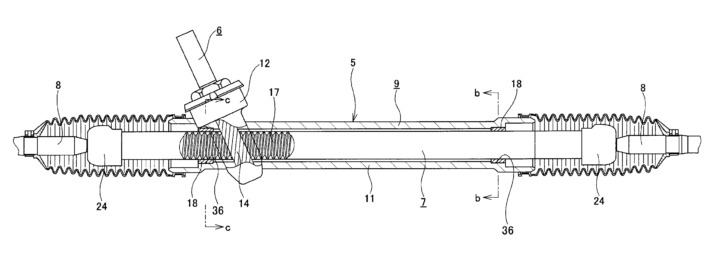
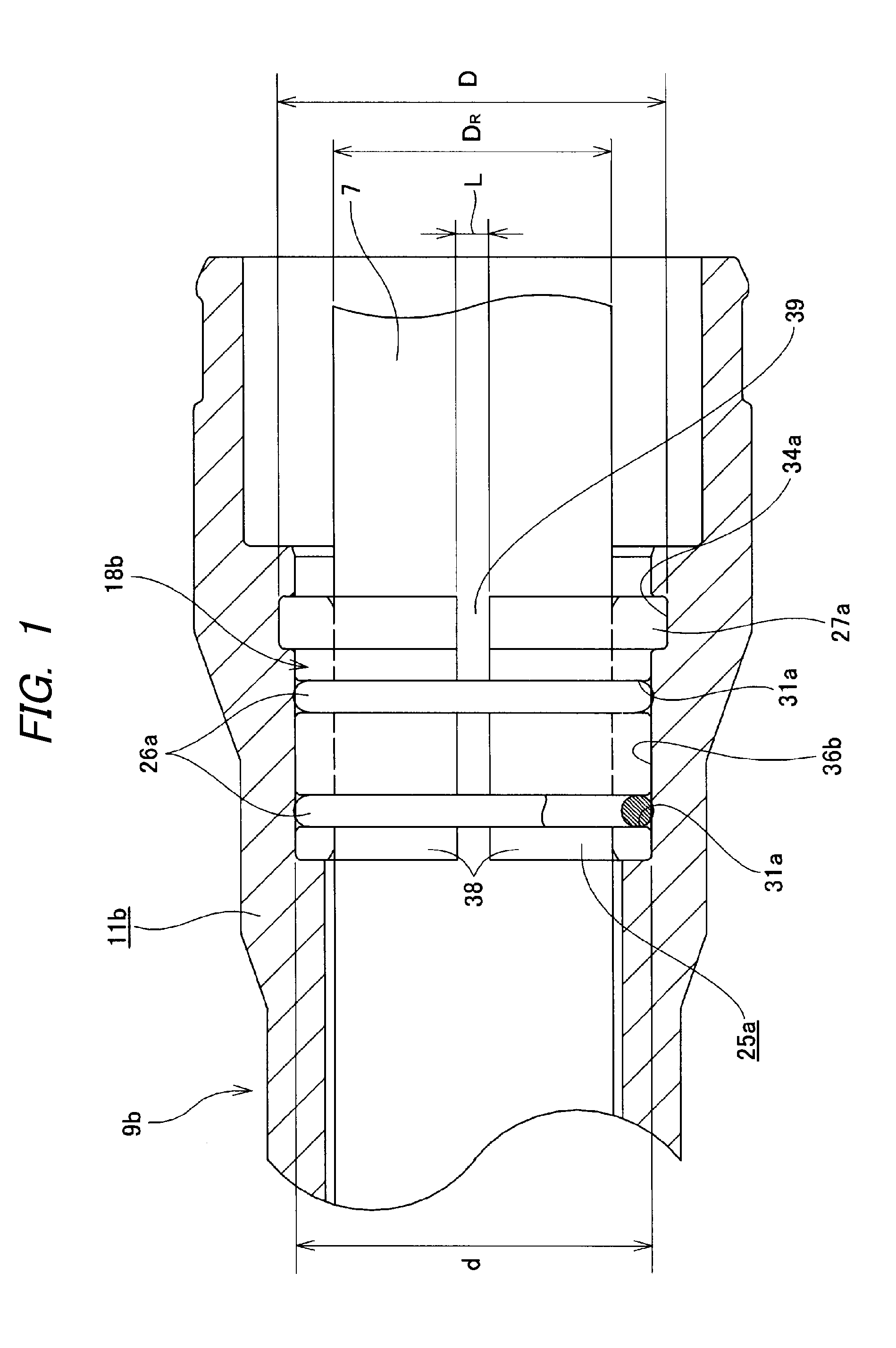
[0061]FIGS. 1 to 4 show the present invention. The present example is characterized in that a structure capable of supporting the rack shaft 7 in a fit-and-hold portion 36b without play and for sufficiently ensuring abrasion resistance is realized while the rise of manufacturing cost is curbed. Since the configurations and operations of other portions are similar to those of the above-described conventional structure shown in FIGS. 16 to 19, overlapping illustrations and descriptions will be omitted.

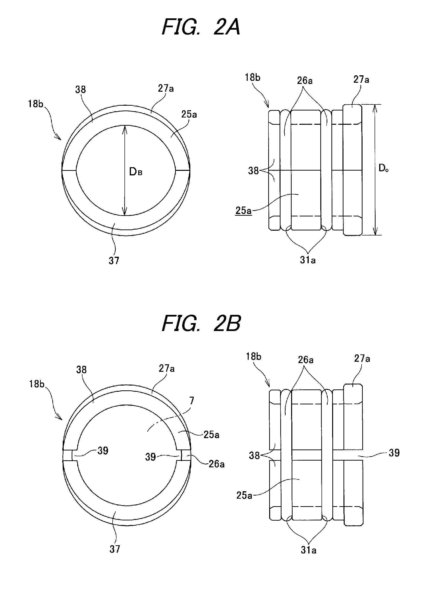
[0062]A guide bush 18b of the present example is configured so as to be cylindrical as a whole and that the outside diameter can be increased and decreased by combining a pair of bush elements 38, 38 that are each semicylindrical. The guide bush 18b includes a cylindrical fitting portion 25a, a pair of elastic rings 26a, 26a and a flange portion 27a. The cylindrical fitting portion 25a has the rack shaft 7 inserted therein, and guides the outer peripheral surface of this rack shaft 7 by ...

second embodiment

[0069]FIGS. 8 to 10 illustrate the present invention. The present example is characterized in that a structure of a guide bush 18f that enables easy attachment to the fit-and-hold portion 36b is provided. Since the configurations and operations of other portions are similar to those of the foregoing conventional structure shown in FIGS. 16 to 19, overlapping illustrations and descriptions will be omitted.

[0070]The guide bush 18f of the present example is configured so as to be substantially cylindrical as a whole by combining a pair of bush elements 38b, 38c that are each made of a synthetic resin and substantially semicylindrical, and has discontinuous portions (gaps) 39a, 39b at two locations in the circumferential direction (locations opposite to each other in the diametrical direction). That is, according to the present example, the portions between the end faces of the bush elements 38b, 38c with respect to the circumferential direction are the discontinuous portions 39a, 39b. ...


PUM

PropertyMeasurementUnit
Diameteraaaaaaaaaa

Abstract

A guide bush includes a plurality of bush elements combined to form a cylindrical shape as a whole. The plurality of bush elements includes a cylindrical fitting portion. The cylindrical fitting portion is fitted in a fit-and-hold portion of a housing, and has an inner peripheral surface configured to guide an outer peripheral surface of a displacement shaft that has been inserted in the cylindrical fitting portion in an axially displaceable manner. The diameter of the circumscribed circle of the plurality of bush elements in a state in which the end faces of the plurality of bush elements with respect to a circumferential direction abut each other is not greater than the inside diameter of the fit-and-hold portion.

Description

TECHNICAL FIELD[0001]The present invention relates to a guide bush that supports a shaft so as to be displaceable in an axial direction with respect to a housing, and a rack-and-pinion steering gear unit of a vehicle steering apparatus of using the guide bush.BACKGROUND ART[0002]Conventionally, a vehicle steering apparatus having a rack-and-pinion steering gear unit has been widely used. FIGS. 16 to 20 illustrate an example of the conventional structure of such a steering apparatus. This steering apparatus has, as the general structure is shown in FIG. 16, a structure where a desired rudder angle can be provided to a non-illustrated right and left steering wheels by such a manner that the rotary movement of a steering wheel 1 operated by the driver is converted to a linear movement by a rack-and-pinion steering gear unit 5. To realize such a structure, specifically, the steering wheel 1 is fixed to the rear end portion of a steering shaft 2. Together with this, the front end portion...

Claims


Application Information

Patent Timeline
IPC IPC(8): B62D3/12F16C33/04F16C33/20
CPCB62D3/12F16C33/20F16C33/046B62D3/123F16C2326/24F16C29/02F16C2208/00F16C2220/04
Inventor MIZUTANI, HIROTOTERAO, KEITARO
Owner NSK LTD
Why Eureka
Try Eureka