Evaporator and condenser section structure for thermosiphon

a technology of condenser section and thermosiphon, which is applied in the direction of refrigerating machines, tubular elements, lighting and heating apparatus, etc., can solve the problems of less efficient counterflow type devices than closed loop systems, and achieve the effects of less efficient, reduced cost and large overall siz

Inactive Publication Date: 2016-03-03
AAVID THERMALLOY LLV
View PDF0 Cites 25 Cited by
  • Summary
  • Abstract
  • Description
  • Claims
  • Application Information

AI Technical Summary

Benefits of technology

[0006]In accordance with an aspect of the invention, a thermosiphon device may have a closed loop evaporator section combined with a counterflow type condenser section. Generally, thermosiphon devices are made such that both the evaporator and condenser sections operate in a counterflow-type mode, or with a closed loop flow. Counterflow type devices tend to be less efficient than closed loop systems, but are suitable for certain applications and tend to be lower cost systems. On the other hand, closed loop systems can have a larger overall size, e.g., because of the dedicated flow paths and other components. By combining a closed loop evaporator section with a counterflow condenser section, the inventors have found that improved thermal performance in comparison to standard counterflow devices can be provided, but with lower equipment cost and overall size of the system.
[0009]In one embodiment, the evaporator section is formed as a flat tube that is bent at a location where the liquid return outlet communicates with the at least one evaporation channel inlet. For example, the flat tube may be bent to form a 180 or other degree bend where the liquid return outlet communicates with the at least one evaporation channel inlet. In addition, or alternately, an outlet end of the flat tube at the evaporator channel outlet may be twisted about an axis along a length of the flat tube at the outlet end, and / or an inlet end of the flat tube at the liquid return path inlet may be twisted about an axis along a length of the flat tube at the inlet end. For example, inlet and / or outlet ends of the flat tube may be twisted 90 degrees about the axes. This type of arrangement may allow for simplified connections between the evaporator section and other parts of the thermosiphon device, e.g., the need for connectors to provide bends in the system flow path may be eliminated and replaced by bent / twisted tube sections.
[0010]In another aspect of the invention, a thermosiphon device may include a closed loop condenser section that has a liquid bypass or exit path for condensed liquid in the vapor supply path of the condenser section. This arrangement may reduce the concern regarding condensate forming in the vapor supply path, e.g., allowing the vapor supply path to be positioned closely to condensing channels of the device in such a way that condensate may form in the vapor supply path. For example, a thermosiphon cooling device includes a closed loop evaporator section having at least one evaporation channel with an inlet and an outlet and arranged to receive heat and evaporate a liquid in the at least one evaporation channel to deliver vapor to the evaporation channel outlet. A liquid return path, having an inlet and outlet, may deliver condensed liquid to the at least one evaporation channel. A condenser section may have a vapor supply channel arranged to receive vapor from the outlet of the at least one evaporation channel and deliver vapor to an upper end of the at least one condensing channel. The at least one condensing channel may be arranged to transfer heat from the vapor to a surrounding environment to condense the vapor to a liquid which flows downwardly in the condensing channel to the liquid return path inlet. The vapor supply channel may carry vapor flow, which is separate from condensed liquid flow in the condensing channels, yet the vapor supply channel may be immediately adjacent the at least one condensing channel. This is in contrast to systems which have a similar closed loop condenser arrangement, but have the vapor supply path physically separated from condensing channels. This separation is typically provided so that vapor in the vapor supply does not prematurely condense, which is known to disrupt the cyclical flow in a thermosiphon. However, the inventors have discovered that a vapor supply path can be provided immediately adjacent one or more condensing channels, and yet may be configured so that gravity-driven cyclical flow is not disrupted. In some embodiments, for example, an area where the vapor supply channel is fluidly connected to the outlet of the evaporator section may be provided with a liquid bypass or other flow path so that condensate in the vapor supply channel may drain to a manifold or other liquid return path of the device.
[0014]In some embodiments, an outlet end of the flat tube at the evaporator channel outlet may be twisted about an axis along a length of the flat tube at the outlet end, and / or an inlet end of the flat tube at the liquid return path inlet may be twisted about an axis along a length of the flat tube at the inlet end. For example, the inlet and outlet ends of the flat tube may be twisted 90 degrees about the axes. This arrangement may allow for relatively compact connections between the evaporator section and other portions of the thermosiphon device without the use of additional connectors. Instead, the tube ends may be twisted as needed to provide a suitably compact and correctly oriented connection.
[0015]In another aspect of the invention, a thermosiphon cooling includes a condenser section having a plurality of condensing channels arranged to receive evaporated liquid and arranged to transfer heat from the evaporated liquid to a surrounding environment to condense the evaporated liquid to a liquid which flows downwardly in the condensing channels. The condenser section may include first and second panels that sandwich a channel-defining member so as to form the plurality of condenser channels, with the first and second panels defining a lower manifold that fluidly connects lower ends of the condenser channels. Such an arrangement may provide a simple and efficient design which eliminates a variety of parts, such as an end cap for the upper ends of the condenser channels. In some embodiments, the first and second panels define an upper manifold that fluidly connects upper ends of the condenser channels, e.g., so the condenser section can be used as a closed loop type device. Alternately, or in addition, the channel-defining member may define a vapor supply channel, e.g., that is located between sets of condensing channels.
[0016]In another illustrative embodiment, a thermosiphon cooling device includes an evaporator section with a tube and an axially extending separation wall within the tube to separate at least one evaporation channel from a liquid return path in the tube. The axially extending separation wall may have a bottom end that is positioned away from a lower end of the tube and define the inlet for the at least one evaporation channel. This configuration may provide for a simplified evaporator device that includes a single tube and a plate or other element positioned inside the tube to function as a separation wall. In some embodiments, the tube may also define a condenser section, e.g., an inner surface of the tube may have fins or channels that define one or more condensing channels, one or more evaporation channels, and one or more liquid return paths. In some cases, the fins or channels at the at least one evaporation channel are different from the fins or channels at the liquid return path. For example, the channels or grooves at the evaporation channels may be arranged to enhance liquid boiling, whereas the channels or grooves at the liquid return path may be arranged to enhance condensate consolidation and flow.

Problems solved by technology

Counterflow type devices tend to be less efficient than closed loop systems, but are suitable for certain applications and tend to be lower cost systems.

Method used


Image

  • Evaporator and condenser section structure for thermosiphon
  • Evaporator and condenser section structure for thermosiphon
  • Evaporator and condenser section structure for thermosiphon

Examples


Embodiment Construction

[0034]Aspects of the invention are not limited in application to the details of construction and the arrangement of components set forth in the following description or illustrated in the drawings. Other embodiments may be employed and aspects of the invention may be practiced or be carried out in various ways. Also, aspects of the invention may be used alone or in any suitable combination with each other. Thus, the phraseology and terminology used herein is for the purpose of description and should not be regarded as limiting.

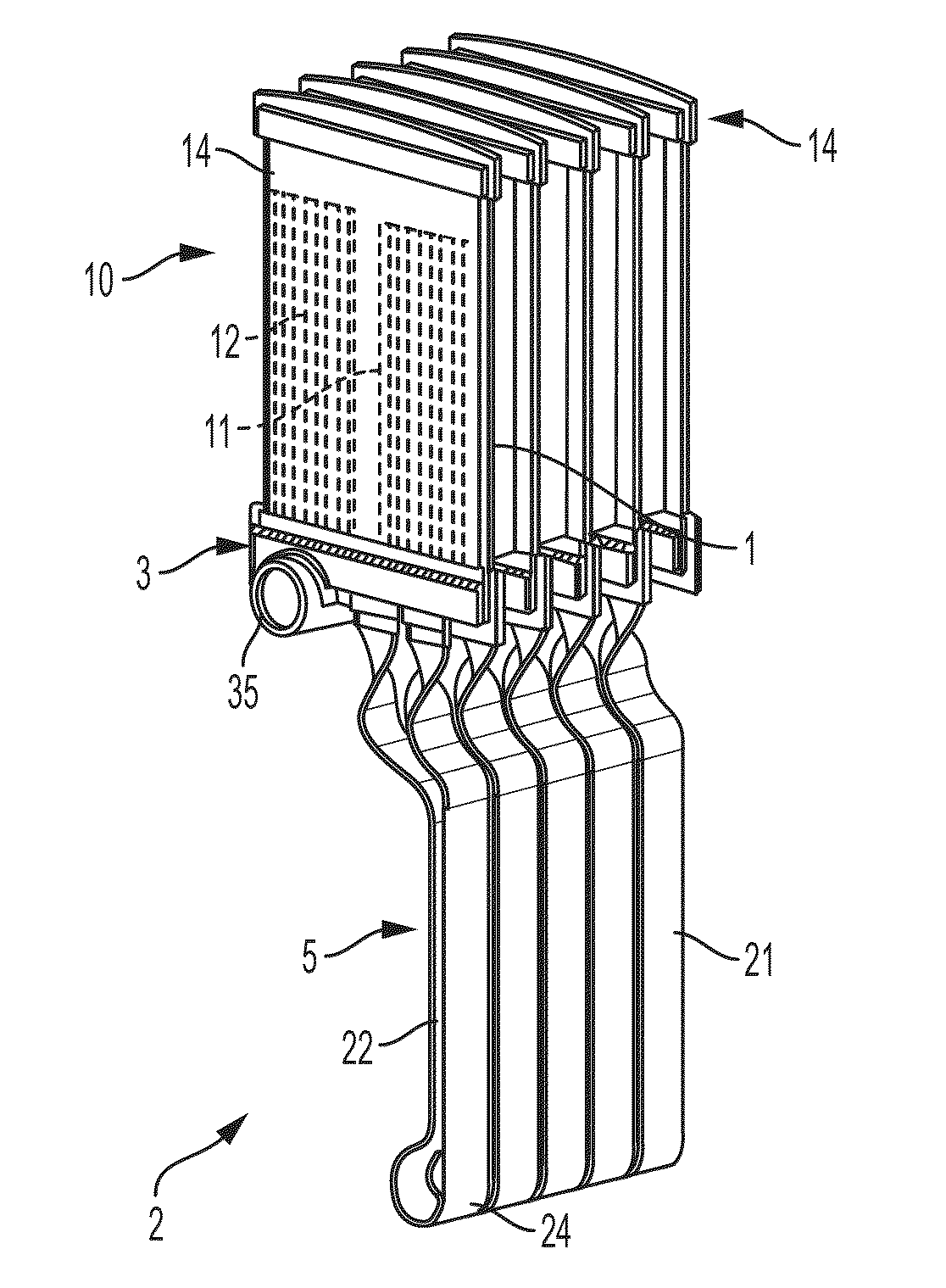
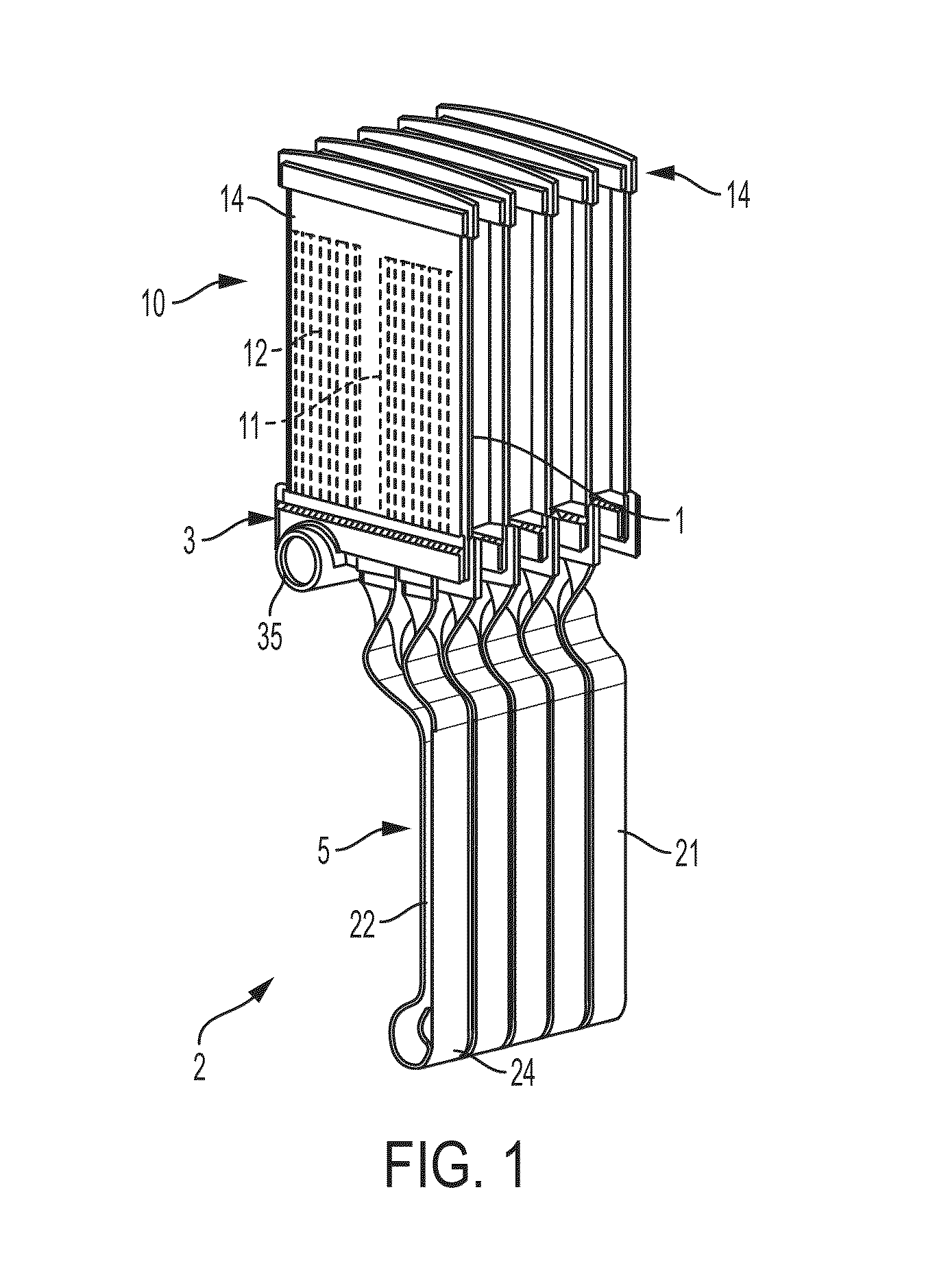
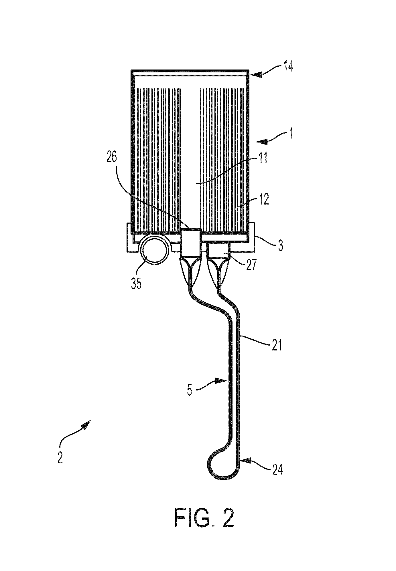
[0035]In accordance with an aspect of the invention, a thermosiphon cooling device includes an evaporator section formed as a flat tube that is bent at a location where the liquid return outlet communicates with the at least one evaporation channel inlet. For example, the evaporator section may include at least one evaporation channel having an inlet and a liquid return path having an outlet that is fluidly coupled to the evaporation channel inlet, where the a...


PUM


Abstract

A thermosiphon device includes a closed loop evaporator section having one or more evaporation channels that are fed by a liquid return path, and a condenser section with one or more condensing channels. The condenser section may include a vapor supply path that is adjacent one or more condensing channels, e.g., located between two sets of condensing channels. Evaporator and / or condenser sections may be made from a single, flat bent tube, which may be bent about an axis parallel to the plane of the flat tube to form a turnaround and / or twisted about an axis along a length of the tube at the tube ends. A single tube may form both evaporator and condenser sections of a thermosiphon device, and an axially extending wall inside the tube in the evaporator section may separate an evaporator section from a liquid return section.

Description

CROSS REFERENCE TO RELATED APPLICATION[0001]This application claims the benefit of U.S. Provisional Application No. 62 / 044,604, filed Sep. 2, 2014, which is hereby incorporated by reference in its entirety.BACKGROUND OF THE INVENTION[0002]1) Field of Invention[0003]This invention relates generally to thermosiphon devices and other heat transfer devices that employ a two-phase fluid for cooling.[0004]2) Description of Related Art[0005]Thermosiphon devices are widely used for cooling systems, such as integrated circuits and other computer circuitry. For example, U.S. Patent Publication 2013 / 0104592 discloses a thermosiphon cooler used to cool electronic components located in a cabinet or other enclosure.SUMMARY OF THE INVENTION[0006]In accordance with an aspect of the invention, a thermosiphon device may have a closed loop evaporator section combined with a counterflow type condenser section. Generally, thermosiphon devices are made such that both the evaporator and condenser sections...

Claims


Application Information

Patent Timeline
Patent Type & Authority Applications(United States)
IPC IPC(8): F28D15/02
CPCF28D15/0266F28D15/025F28D15/0233F28D15/046F25B39/02F25B39/04F28F1/022F28F1/14
Inventor ESPERSEN, MORTEN, SOEGAARDANGRISANI, MARIA, LUISAJENSEN, DENNIS, N.KANG, SUKHVINDER, S.
Owner AAVID THERMALLOY LLV
Why Eureka
Try Eureka