
Electronic display designed for reduced reflections

Pending Publication Date: 2016-03-03
ELBIT SYST LTD
View PDF5 Cites 15 Cited by
  • Summary
  • Abstract
  • Description
  • Claims
  • Application Information

AI Technical Summary

Benefits of technology

The invention is a system that reduces reflection when using electronic displays. It uses a light directing medium to steer viewing cones into a specific eye motion box. This helps to reduce glare and other reflections that can make it difficult to see the display clearly.

Problems solved by technology

This method tends to be prohibiting in adding additional images.
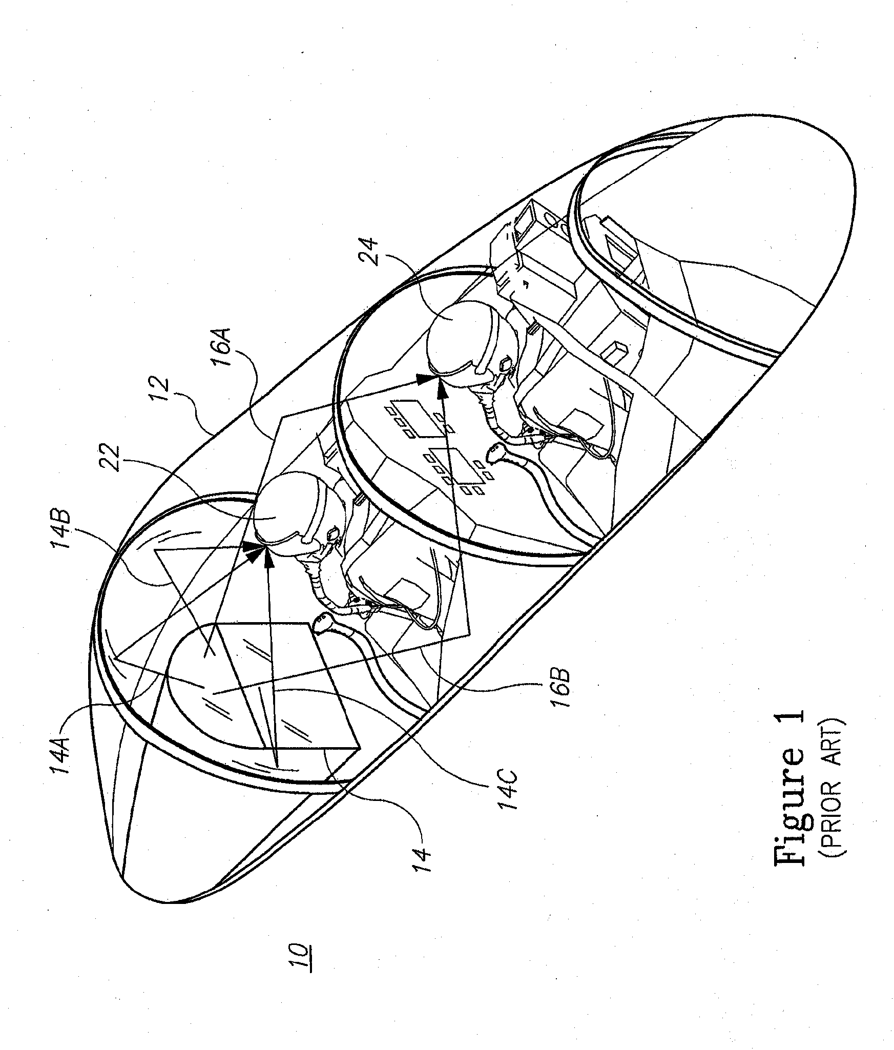
At night, such reflections are undesirable because they clutter the view of the darkened scene outside the aircraft canopy.
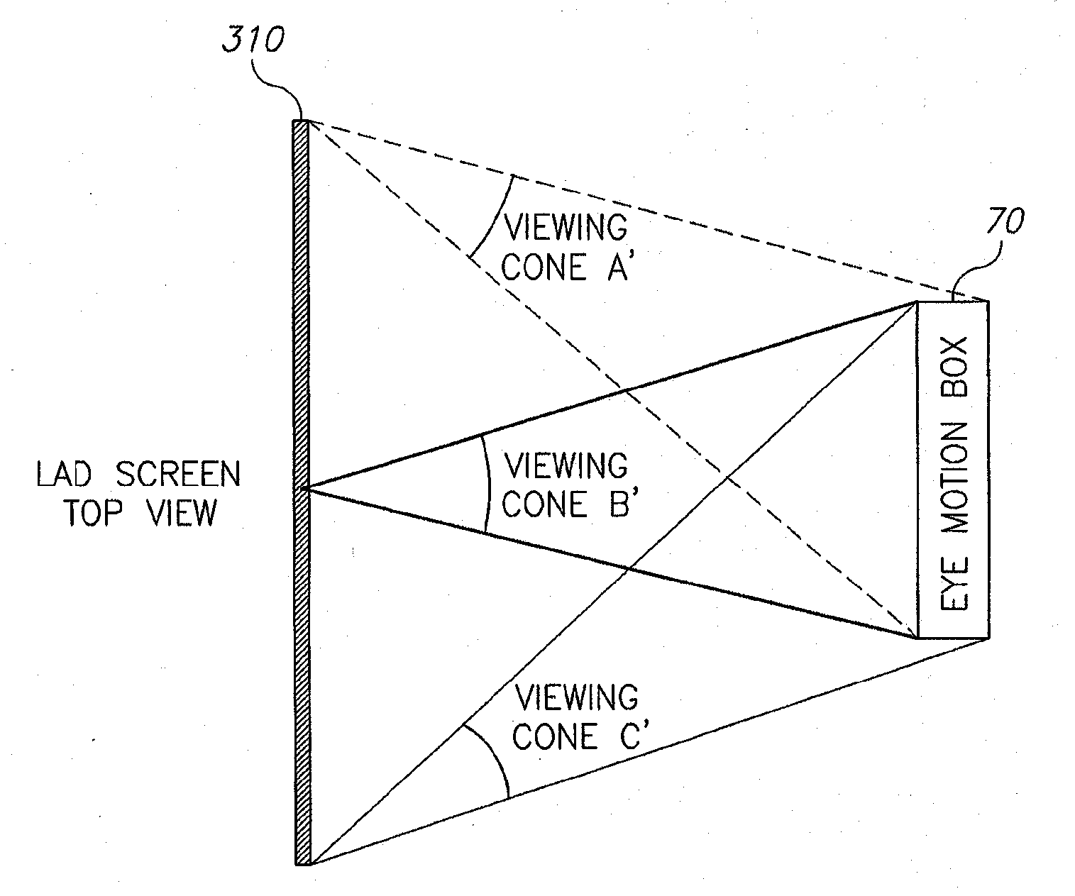
It is important to note that the light emitted from the display beyond the viewing cones is clocked or severely reduces so that viewing the light coming from the display beyond the viewing cone is not possible.
However, due to the use of optical fibers which are limited in the opening angle of the light flowing through then and the minimal width of light steering medium 300, it would be impossible to get cone A, B, and C overlap in a specified eye motion box in a case the display is a LAD.

Method used


Image

  • Electronic display designed for reduced reflections
  • Electronic display designed for reduced reflections
  • Electronic display designed for reduced reflections

Examples


Embodiment Construction

[0021]With specific reference now to the drawings in detail, it is stressed that the particulars shown are by way of example and for purposes of illustrative discussion of the preferred embodiments of the present invention only, and are presented in the cause of providing what is believed to be the most useful and readily understood description of the principles and conceptual aspects of the invention. In this regard, no attempt is made to show structural details of the invention in more detail than is necessary for a fundamental understanding of the invention, the description taken with the drawings making apparent to those skilled in the art how the several forms of the invention may be embodied in practice.

[0022]Before explaining at least one embodiment of the invention in detail, it is to be understood that the invention is not limited in its application to the details of construction and the arrangement of the components set forth in the following description or illustrated in ...


PUM


Abstract

An optical system that reduces reflections from an electronic display is provided herein. The optical system may include an electronic display; and a light directing medium configured to steer a plurality of viewing cones into an eye motion box facing said display so that said viewing cones overlap at least partially at the eye motion box plane, wherein a viewing cone is a geometric location only within which a viewer can see light coming from said electronic display.

Description

FIELD OF THE INVENTION[0001]The present invention relates to electronic displays and more particularly, to such displays that produce reduced level reflections from ambience.BACKGROUND OF THE INVENTION[0002]In recent years, there is a growing need to introduce Large Area Displays (LAD) in critical applications. One of the most demanding applications for LAD is in the cockpit of aircraft. There is growing and insatiable need in presenting flight information, navigation information, and sensor and mission information. Traditionally, the classical solution for such cockpits was the use of several Multi-Function-Displays (MFD). The installation of multiple displays results in a very rigid layout and formatting of the displayed images. Since the size of the display is given, the information format is given. This method tends to be prohibiting in adding additional images. On the other hand the introduction of Large Area Displays allows the dynamic allocation of display area in accordance ...

Claims


Application Information

Patent Timeline
IPC IPC(8): G02B27/01G02B5/02
CPCG02B27/0081G02B2207/123G02B27/0101G02B2027/0181G02B2027/012G02B5/0231G02B27/0179G02B27/0093
Inventor AMARILIO, ERRIKOSLANDESBERG, YOLANDA
Owner ELBIT SYST LTD
Learn More