
Power meter with automatic configuration

a technology of automatic configuration and power meters, applied in the direction of instruments, heat measurement, heating types, etc., can solve the problems of affecting the device's performance and utility, the limitation of the number of addressable registers in the modbus device, and the limitations of the devi

Active Publication Date: 2016-03-10
SCHNEIDER ELECTRIC USA INC
View PDF9 Cites 25 Cited by
  • Summary
  • Abstract
  • Description
  • Claims
  • Application Information

AI Technical Summary

Benefits of technology

The present invention is a power meter with automatic configuration capability. It is designed to efficiently measure and calculate the power usage of a three-phase system by using a combination of transformers and voltage "taps" to measure the voltage and current at the cables and panels. The data processing system in the power meter is capable of processing the data from the transformers and displaying it in real-time or for storage. The invention also utilizes the MODBUS RTU serial communication protocol for communication among the devices in the network. The technical effects of the invention include improved efficiency, flexibility, and better data management.

Problems solved by technology

While the MODBUS protocol is a de facto standard for industrial electronic devices, it does have its limitations.
Also, the number of addressable registers in a MODBUS device is limited which can affect the device's performance and utility.
For example, a branch circuit monitor monitoring a large number of circuits and determining several electrical measurement parameters for each circuit generates substantial amounts of data and the limited number of addressable registers can limit the number of circuits monitored by the branch circuit monitor and / or the types of data that can be produced and communicated by the monitor.
Also, the configuration of such a device can be cumbersome and require significant computational resources to determine all the potential data that may be desired.

Method used


Image

  • Power meter with automatic configuration
  • Power meter with automatic configuration
  • Power meter with automatic configuration

Examples


Embodiment Construction

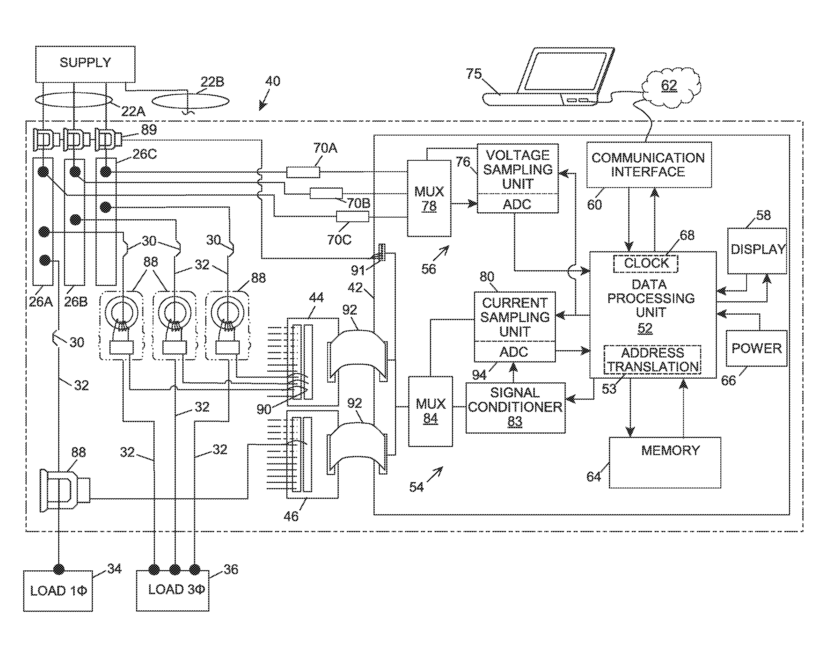
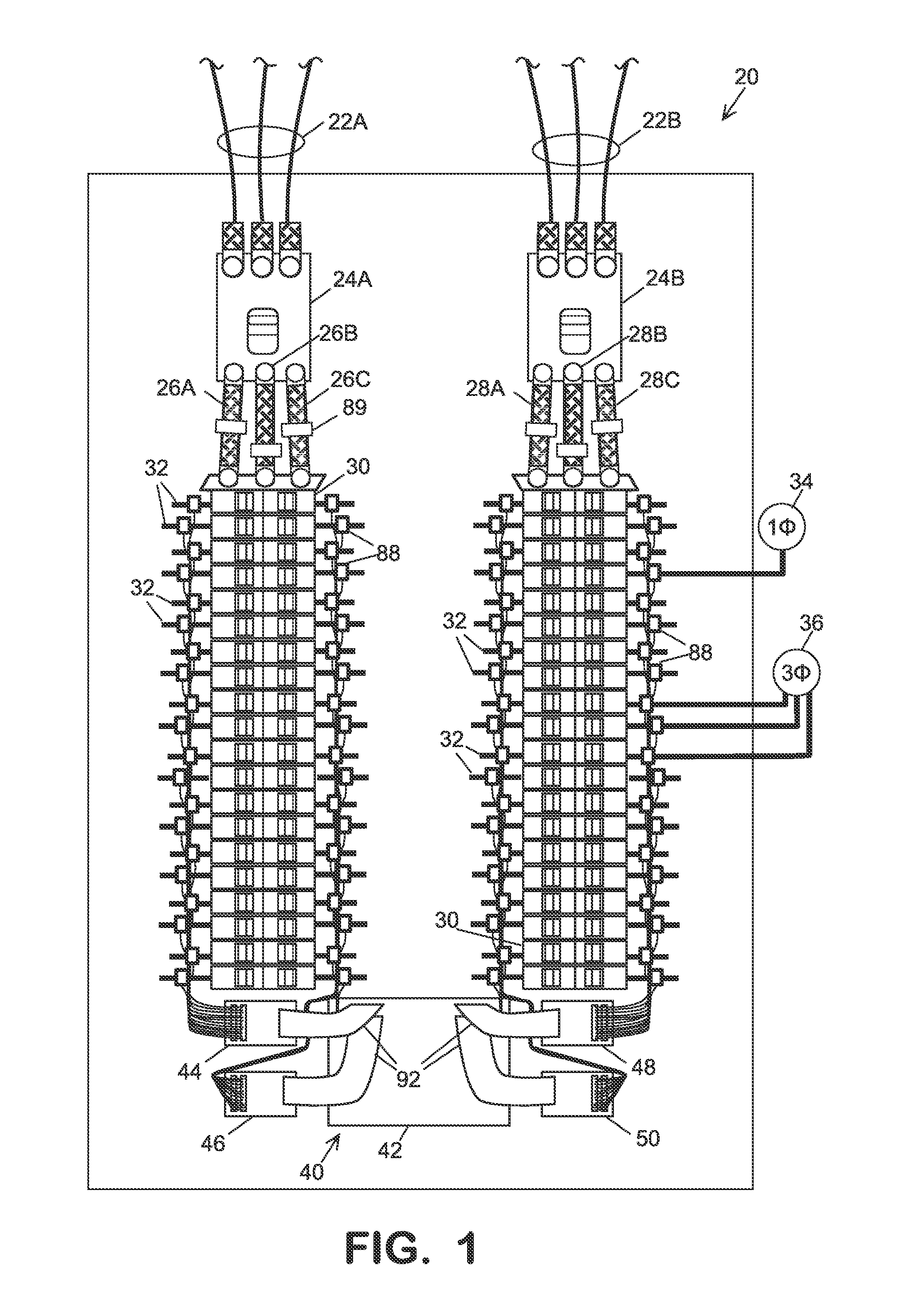
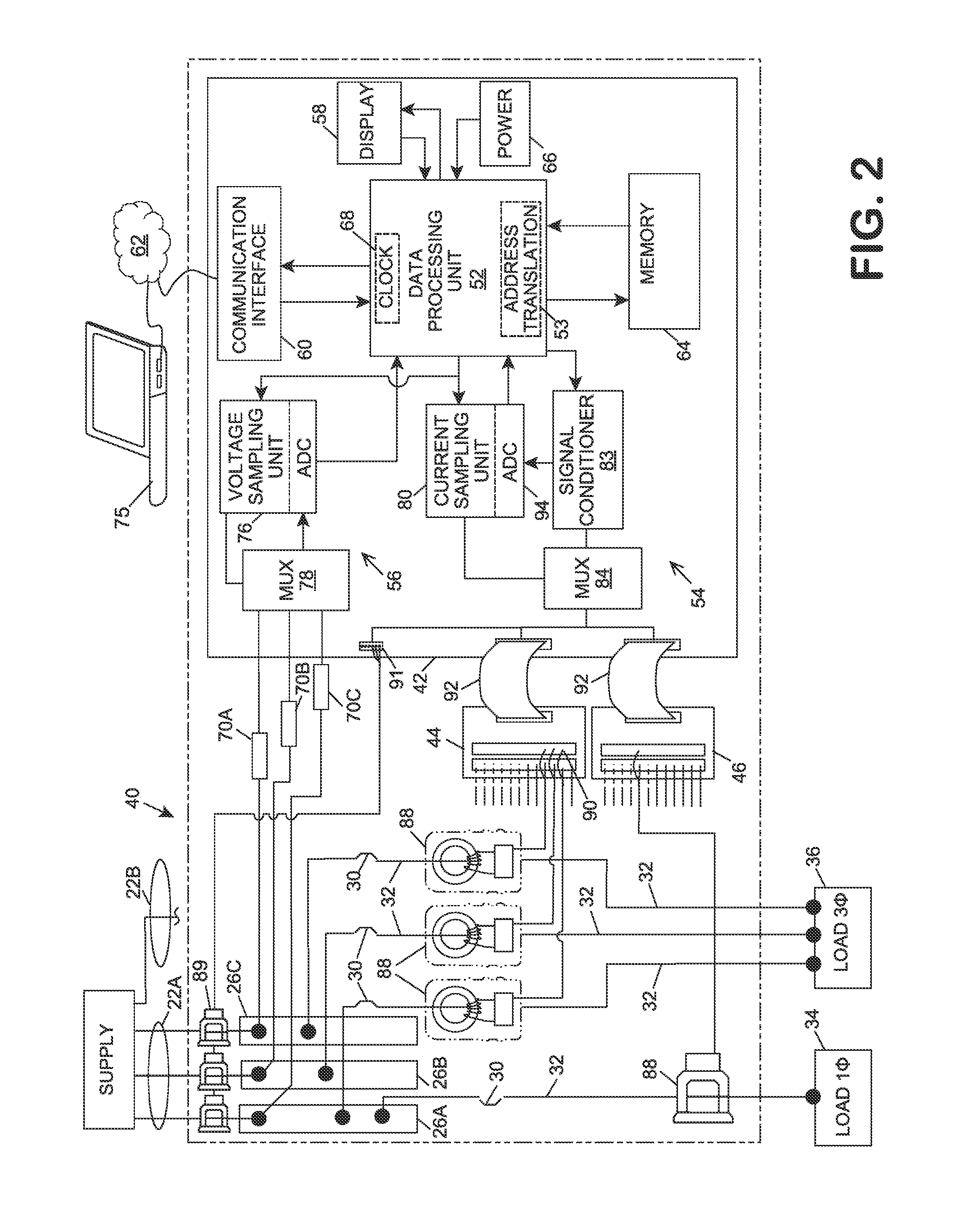
[0016]Electricity delivered by the local utility to a facility's mains is distributed to the various loads in the facility by branch circuits which are conductively connected to the mains at a distribution panel. Referring in detail to the drawings where similar parts are identified by like reference numerals, and, more particularly to FIG. 1, an exemplary distribution panel 20 includes two three-phase mains 22A, 22B which are respectively connected to main circuit breakers 24A, 24B. Each of the phases of each main is connected to a respective bus bar 26A, 26B, 26C and 28A, 28B, 28C. Three of the bus bars extend behind each of two rows of branch circuit breakers 30 that respectively conductively connect one of the bus bars to a branch circuit conductor 32 which is conductively connected to the load(s) of the branch circuit. A single phase load, for example, load 34, is conductively connected to a single bus bar. A two-phase load is connected, typically through two adjacent circuit b...


PUM


Abstract

A power monitoring system includes a plurality of current sensors suitable to sense respective changing electrical current within a respective conductor to a respective load and a conductor sensing a respective voltage potential provided to the respective load. A power monitors determines a type of circuit based upon a signal from at least one of the current sensors and a signal from the conductor, wherein the type of circuit includes at least one of a single phase circuit, a two phase circuit, and a three phase circuit. The power meter configures a set of registers corresponding to the determined type of circuit in a manner such that the configuring is different based upon each of the single phase circuit, two phase circuit, and three phase circuit suitable to provide data corresponding to the determined type of circuit.

Description

CROSS-REFERENCE TO RELATED APPLICATIONS[0001]This application is a continuation of U.S. patent application Ser. No. 14 / 050,496, filed Oct. 10, 2013, which application claims the benefit of U.S. Provisional App. No. 61 / 747,937, filed Dec. 31, 2012,BACKGROUND OF THE INVENTION[0002]The present invention relates generally to a power meter with automatic configuration capability.[0003]Electrical power is provided to many devices, such as large motors, by three separate cables, each of which supplies a single phase of three phase-power. In an ideal system, each of the phases within the respective cable has a phase angle which is generally 120 degrees apart from the other phases. Accordingly, the total power flowing through the three cables to a three-phase load (or from a three-phase generator) may be computed based upon the phase adjusted voltages and the phase adjusted currents.[0004]A sub-metering system generally includes a separate transformer installed on each respective cable of th...

Claims


Application Information

Patent Timeline
Patent Type & Authority Applications(United States)
IPC IPC(8): G01R15/14G01R15/18G01R19/00G01R21/00
CPCG01R15/142G01R21/00G01R19/0092G01R15/18G01R21/133G05F1/00G01R1/00G01K2201/00G01K1/00H01H1/00H01H45/00H01H2203/00
Inventor COOK, MARTINBITSCH, MICHAEL
Owner SCHNEIDER ELECTRIC USA INC
Learn More