

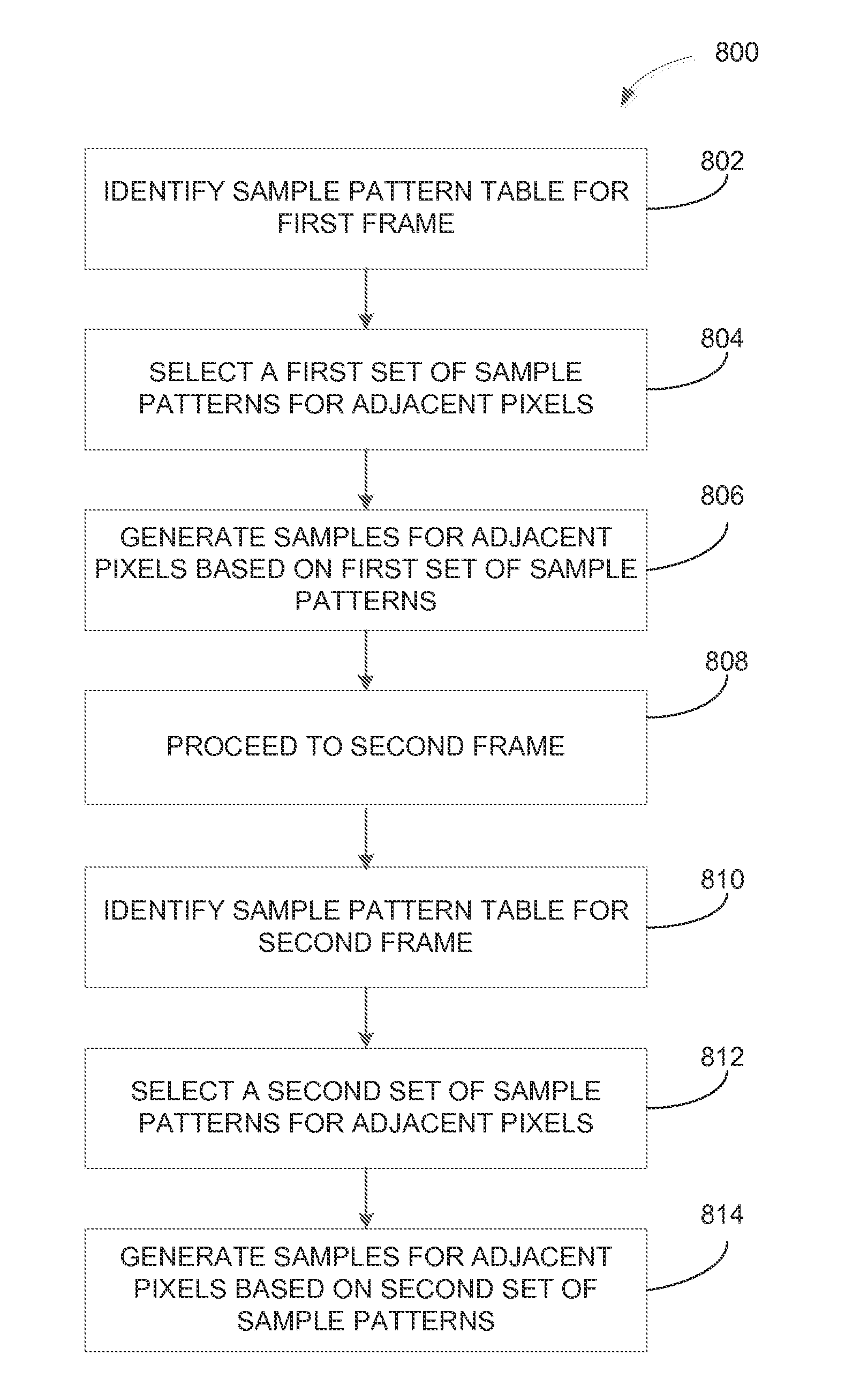
Enhanced Anti-aliasing by varying sample patterns spatially and/or temporally
a sample pattern and spatial and temporal variation technology, applied in image enhancement, instruments, static indicating devices, etc., can solve the problems of inability to generate the image using conventional multi-sampling, and inability to accurately detect the sample form
- Summary
- Abstract
- Description
- Claims
- Application Information
AI Technical Summary
Benefits of technology
Problems solved by technology
Method used
Image

Examples
Embodiment Construction
[0027]In the following description, numerous specific details are set forth to provide a more thorough understanding of the present invention. However, it will be apparent to one of skill in the art that the present invention may be practiced without one or more of these specific details.
System Overview
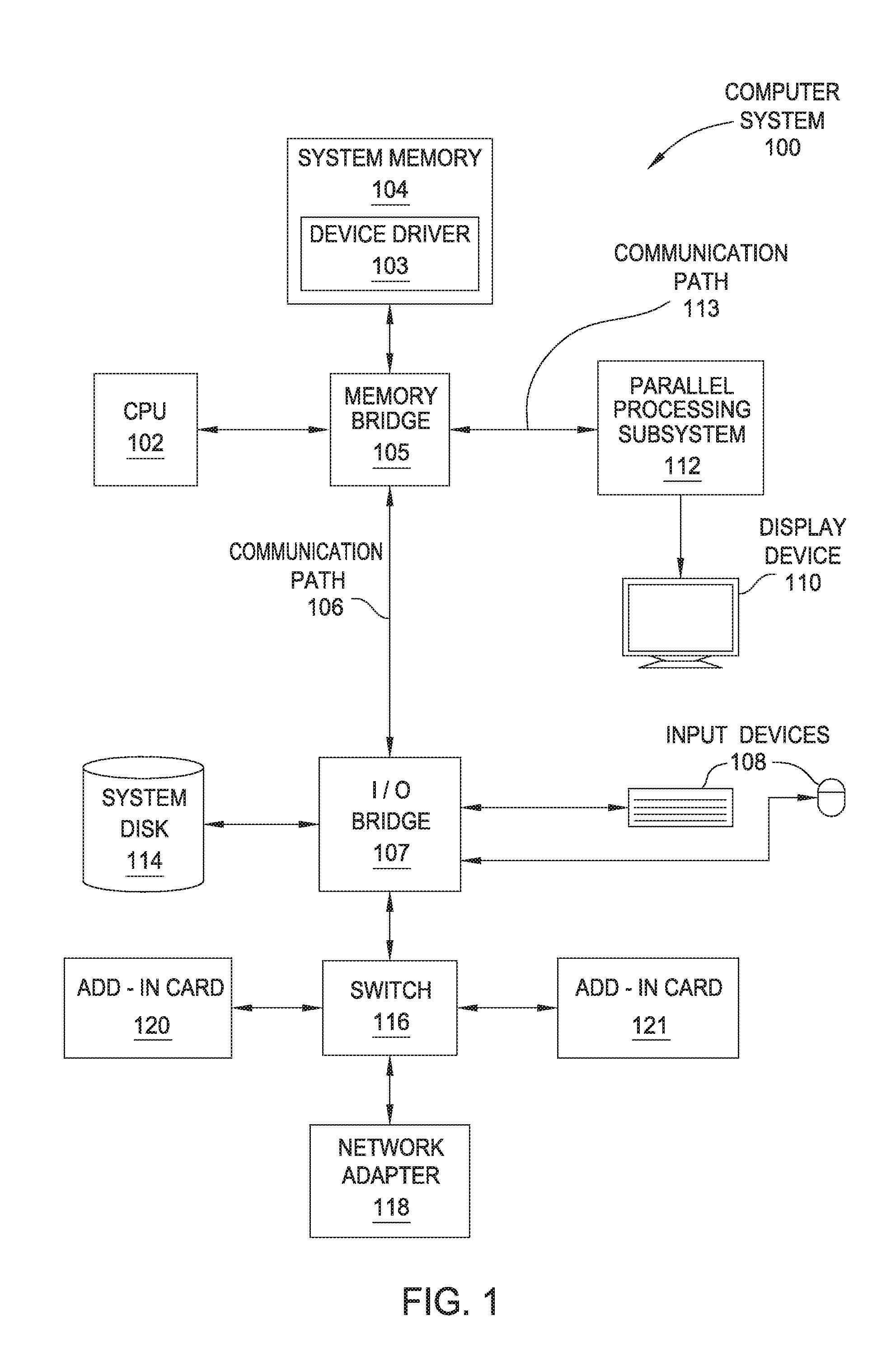
[0028]FIG. 1 is a block diagram illustrating a computer system 100 configured to implement one or more aspects of the present invention. As shown, computer system 100 includes, without limitation, a central processing unit (CPU) 102 and a system memory 104 coupled to a parallel processing subsystem 112 via a memory bridge 105 and a communication path 113. Memory bridge 105 is further coupled to an I / O (input / output) bridge 107 via a communication path 106, and I / O bridge 107 is, in turn, coupled to a switch 116.
[0029]In operation, I / O bridge 107 is configured to receive user input information from input devices 108, such as a keyboard or a mouse, and forward the input information to C...
PUM
 Abstract
Description
Claims
Application Information