Universal cell

Inactive Publication Date: 2016-03-10
LU CHAO CHENG
View PDF6 Cites 0 Cited by
  • Summary
  • Abstract
  • Description
  • Claims
  • Application Information

AI Technical Summary

Benefits of technology

The present invention is about a universal cell that uses multiple cells embedded with diodes to eliminate current-circulation loss when multiple cells are connected in parallel. The cells are connected in an Electrically-Parallel-Coupled way to balance voltage and remove the loss. The voltage balance circuit is designed to fit in a battery container, making it easy to carry and replace. Both the orientation of the diodes and the configuration of the circuitry allow for optimal performance in multiple battery configurations.

Problems solved by technology

1) In a situation of a plurality of battery are connected in parallel, the batteries work at a charge state, since the batteries have different voltage level, the batteries result in generating a current-circulation loss.
2) Under same situation as 1), when the batteries work at a discharge state, it also generates the current-circulation loss.
3) Under same situation as 1), when the batteries don't work at the charge state and the discharge state, the batteries connected each other also generate current-circulation loss until the energy of the batteries are exhausted.
However, any of the above-mentioned situations, it will reduce the effect of charge / discharge, and it is inconvenient for using.

Method used


Image

  • Universal cell
  • Universal cell
  • Universal cell

Examples


first embodiment

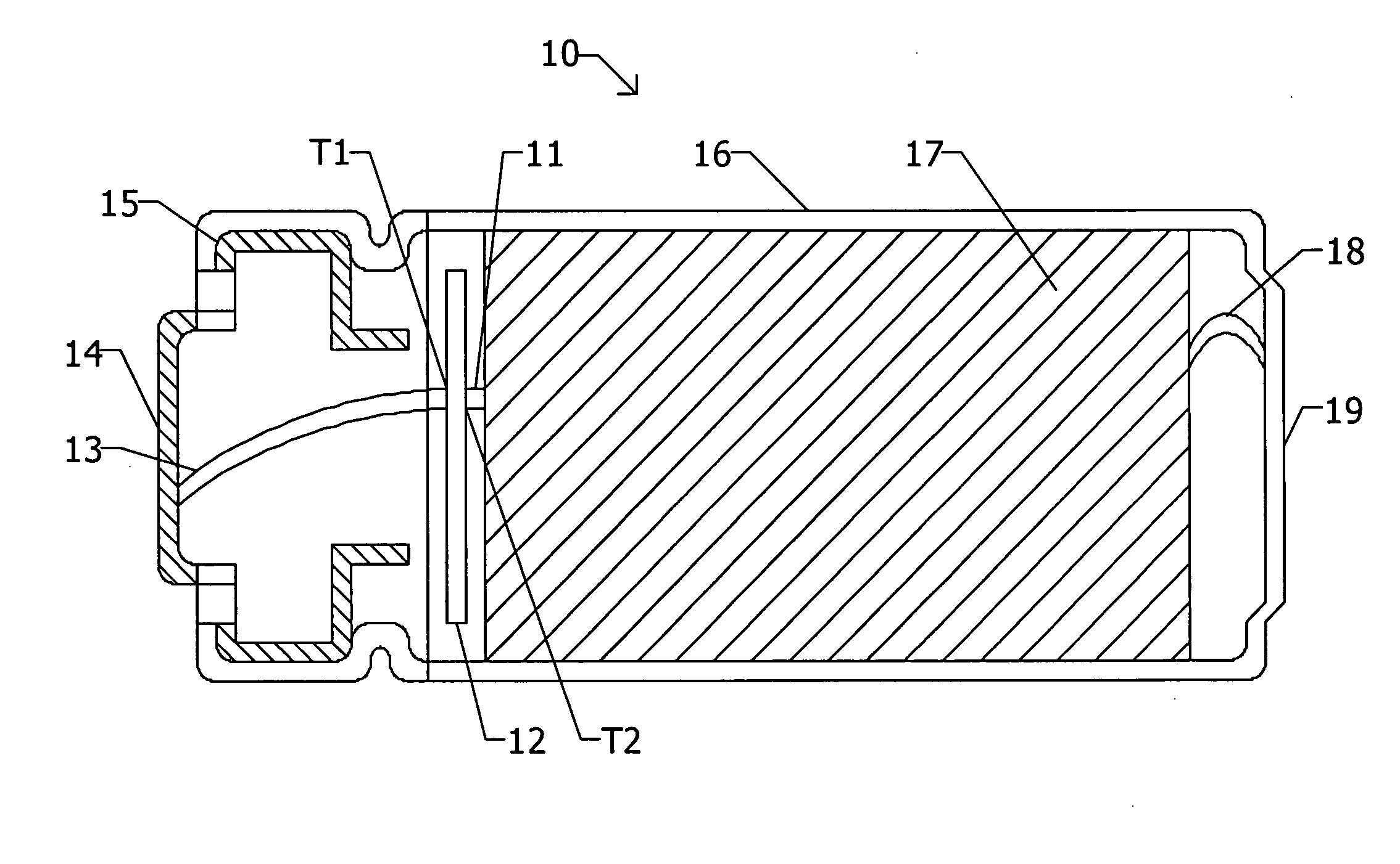
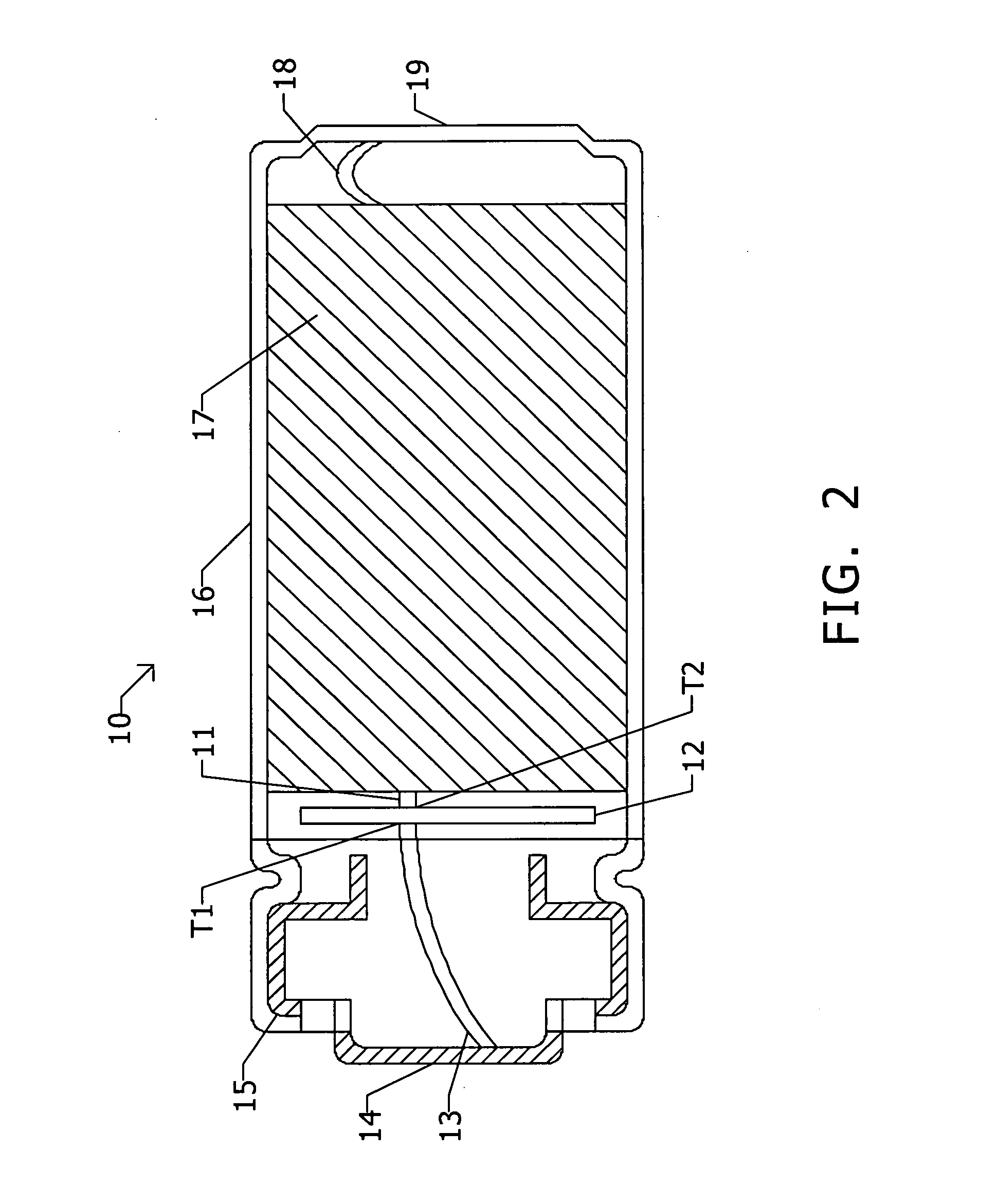
[0025]Refer to FIG. 2, illustrate a sectional view of universal cell of first embodiment of the present invention. In FIG. 2, the universal cell 10 includes a positive terminal 14, a first conductor 13, a voltage balance circuit 12, a positive tab 11, an electrode spiral 17, a negative tab 18, a negative terminal 19, and a battery container 16.

[0026]The positive terminal 14 is connected with an external first circuit (not shown).

[0027]The first conductor 13 includes two terminals. One terminal of the first conductor 13 is connected with the positive terminal 14, and another terminal of the first conductor 13 is connected with a terminal of the voltage balance circuit 12.

[0028]The voltage balance circuit 12 includes two terminals T1, T2. The terminal T1 of the voltage balance circuit 12 is connected with another terminal of the first conductor 13, and another terminal T2 of the voltage balance circuit 12 is connected with a terminal of the positive tab 11. The detail structure of vol...

second embodiment

[0039]Refer to FIG. 4, illustrate a sectional view of universal cell of second embodiment of the present invention. In FIG. 4, the universal cell 10 includes a positive terminal 14, a positive tab 11, an electrode spiral 17, a negative tab 18, a voltage balance circuit 12, a negative terminal 19, a second conductor 20, and a battery container 16.

[0040]The positive terminal 14 is connected with an external first circuit (not shown).

[0041]The positive tab 11 includes two terminals, one terminal of the positive tab 11 is connected with the positive terminal 14, and another terminal of the positive tab 11 is connected with the electrode spiral 17.

[0042]The electrode spiral 17 includes two terminals, one terminal of the electrode spiral 17 is connected with another terminal of the positive tab 11, and another terminal of the electrode spiral 17 is connected with one terminal of the negative tab 18.

[0043]The negative tab 18 includes two terminals, one terminal of the negative tab 18 is co...


PUM


Abstract

This invention is related to a universal cell, the universal cell includes a positive terminal, a first conductor, a voltage balance circuit, a positive tab, an electrode spiral, a negative tab, a negative terminal, and battery container. The universal cell utilizes a characteristic of voltage balance circuit that the universal cell can be connected with another universal cell in parallel without generating a current-circulation loss at an idle state, a charge state, or a discharge state.

Description

FIELD OF THE INVENTION[0001]The present invention relates to a universal cell, in particular a universal cell to converter a chemical energy of a cell to electrical energy, the present invention utilizes a characteristic of voltage balance circuit that connect with a purity of universal cells in parallel for eliminating a current-circulation loss generated by the battery work at an idle state, a charge state and a discharge state.BACKGROUND OF THE INVENTION[0002]Traditional, reference to FIG. 1, FIG. 1 is shown as sectional view of a battery of prior art.[0003]Reference to prior art, the battery is a lithium ion cell 2 comprises a cell cap subassembly 22, a positive terminal 24, a positive tab 26, an insulator 28, an electrode spiral 210, a negative tab 212, a negative terminal 214, and a battery container 216. The prior art discloses a method for connecting the positive tab 26 with the positive terminal 24. In addition, it also reference to other prior arts.[0004]However, the prior...

Claims


Application Information

Patent Timeline
IPC IPC(8): H01M10/42
CPCH01M2010/4271H01M10/4257Y02E60/10
Inventor LU, CHAO-CHENG
Owner LU CHAO CHENG
Why Eureka
Try Eureka