Drive machine for an elevator and an elevator

a technology of drive machine and elevator, which is applied in the direction of elevator, transportation and packaging, hoisting equipment, etc., can solve the problems of difficult to design one type of elevator suitable for efficient operation, the size and shape of the elevator are often limited, and the building cannot always be designed in every way optimal for the elevator, etc., to achieve good adaptability of the drive machine and save space

Active Publication Date: 2016-03-17
KONE CORP
View PDF1 Cites 6 Cited by
  • Summary
  • Abstract
  • Description
  • Claims
  • Application Information

AI Technical Summary

Benefits of technology

[0006]It is brought forward a new drive machine for an elevator, comprising a motor module comprising at least a motor, a drive shaft, and a first transmission wheel all provided with a common rotational axis (X1) and connected coaxially to each other, the drive shaft particularly having the motor on one end and the transmission wheel on the other end. The drive machine further comprises a traction module comprising at least a traction wheel engageable with elevator hoisting ropes, and a second transmission wheel, all provided with a common rotational axis (X2) and connected coaxially to each other. The motor module and the traction module are positioned side by side with their rotational axes (X1, X2) parallel, such that the traction wheel and the drive shaft are side by side, and the first and second transmission wheels are side by side. The drive machine further comprises an endless drive member pa

Problems solved by technology

In cases where a new elevator is installed in a new building, the building cannot always be designed in every way optimal for the elevator.
For instance, the size and shape of the spaces available for the elevator are often limited.
This makes it challenging to design one type of elevator suitable to function efficiently in many different elevator environments.
Especially, modernization of old elevators requires often tailored elevator design, because the modernized elevator design is often very limi

Method used


Image

  • Drive machine for an elevator and an elevator
  • Drive machine for an elevator and an elevator
  • Drive machine for an elevator and an elevator

Examples


Embodiment Construction

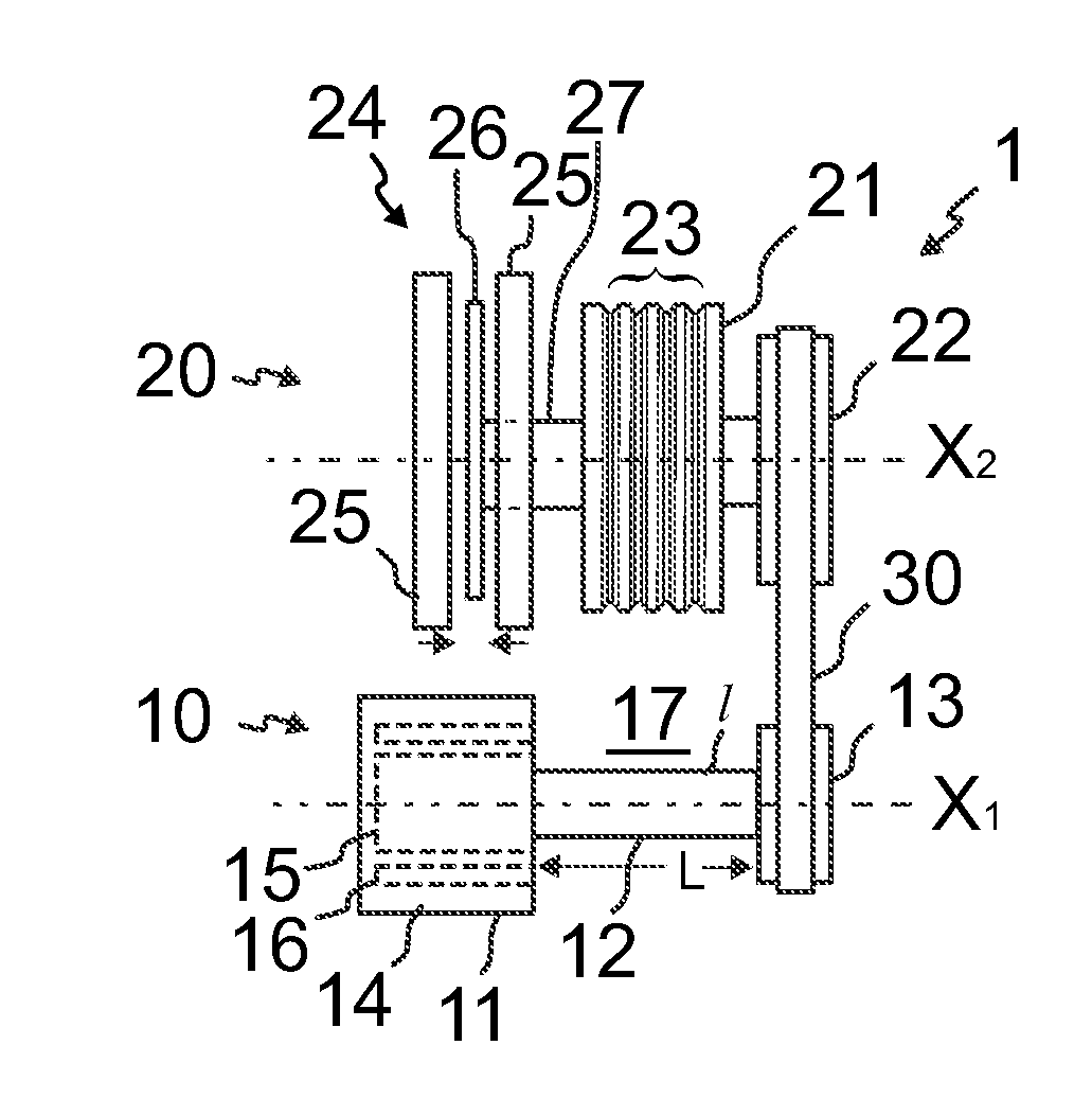
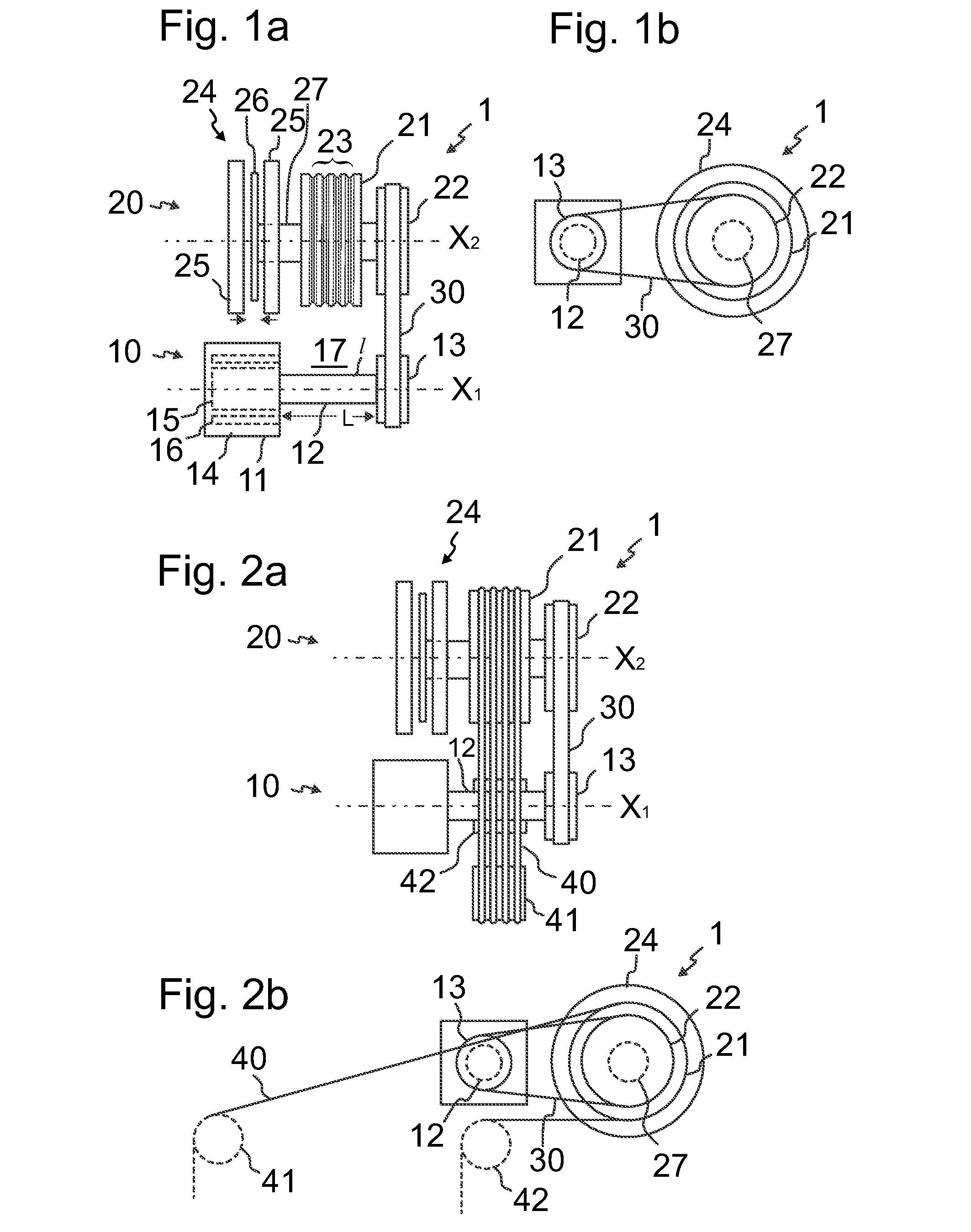
[0047]FIGS. 1a and 1b illustrate a drive machine 1 for an elevator according to a preferred embodiment. FIGS. 2a and 2b illustrate this drive machine when a roping 40 of an elevator is guided to pass around the traction wheel 21 of the drive machine 1. The drive machine 1 comprises a motor module 10 and a traction module 20 positioned side by side and connected to each other. For the purpose of braking the rotation of the traction wheel 21, the drive machine 1 comprises a brake 24. The drive machine 1 further comprises a frame (not shown in FIGS. 1a and 1b) on which the motor module 10 and the traction module 20 are mounted. The motor module 10 comprises a motor 11, a drive shaft 12, and a first transmission wheel 13 all provided with a common rotational axis X1 and connected coaxially to each other the drive shaft 12 having the motor 11 on one end and the transmission wheel 13 on the other end. The traction module 20 comprises a traction wheel 21, which is engageable with elevator ...


PUM


Abstract

A drive machine for an elevator includes a motor module including at least a motor, a drive shaft, and a first transmission wheel, which are provided with a common rotational axis and connected coaxially to each other. The drive machine further includes a traction module including at least a traction wheel engageable with elevator hoisting ropes, and a second transmission wheel, which are provided with a common rotational axis and connected coaxially to each other. The motor module and the traction module are positioned side by side with their rotational axes parallel, such that the traction wheel and the drive shaft are side by side, and the first and second transmission wheels are side by side. The drive machine further includes an endless drive member passing around the first and second transmission wheels. An elevator comprising said drive machine is also disclosed.

Description

FIELD OF THE INVENTION[0001]The invention relates to a drive machine of elevator and an elevator. The elevator is in particular of the type meant for transporting passengers and / or goods.BACKGROUND OF THE INVENTION[0002]An elevator typically comprises a counterweight and an elevator car connected to each other with hoisting ropes. Typically, the elevator further comprises a drive machine having a motor-driven traction wheel around which the ropes pass. The drive machine is usually positioned in a machine room located close to the hoistway in which the elevator car and the counterweight travel.[0003]In cases where a new elevator is installed in a new building, the building cannot always be designed in every way optimal for the elevator. For instance, the size and shape of the spaces available for the elevator are often limited. Nevertheless, the elevator needs to fulfill numerous requirements related to its performance and features. This makes it challenging to design one type of ele...

Claims


Application Information

Patent Timeline
IPC IPC(8): B66B11/04B66B1/36B66B9/00B66B11/08
CPCB66B11/04B66B1/365B66B11/08B66B11/0476B66B9/00B66D5/14
Inventor METSANEN, AKILAPPALAINEN, JOUNIJUURIOKSA, MARTTIHALLIKAINEN, PEKKAKORVENRANTA, SAKARI
Owner KONE CORP
Why Eureka
Try Eureka