Sample dispenser for an analytical device
a technology for analysing devices and sample dispensers, which is applied in the direction of sampling, measurement devices, instruments, etc., can solve the problem of at any rate not being able to switch back and forth in an arbitrary number, and achieve the effect of suppressing contamination effects and simplifying design
- Summary
- Abstract
- Description
- Claims
- Application Information
AI Technical Summary
Benefits of technology
Problems solved by technology
Method used
Image
Examples
first embodiment
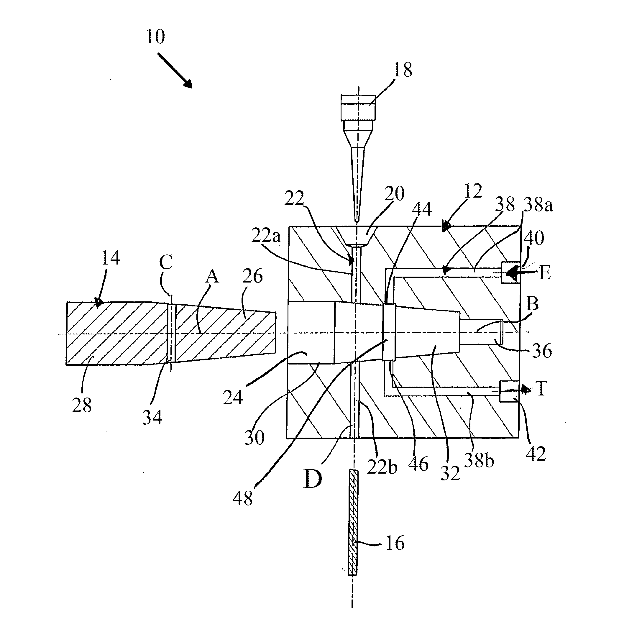
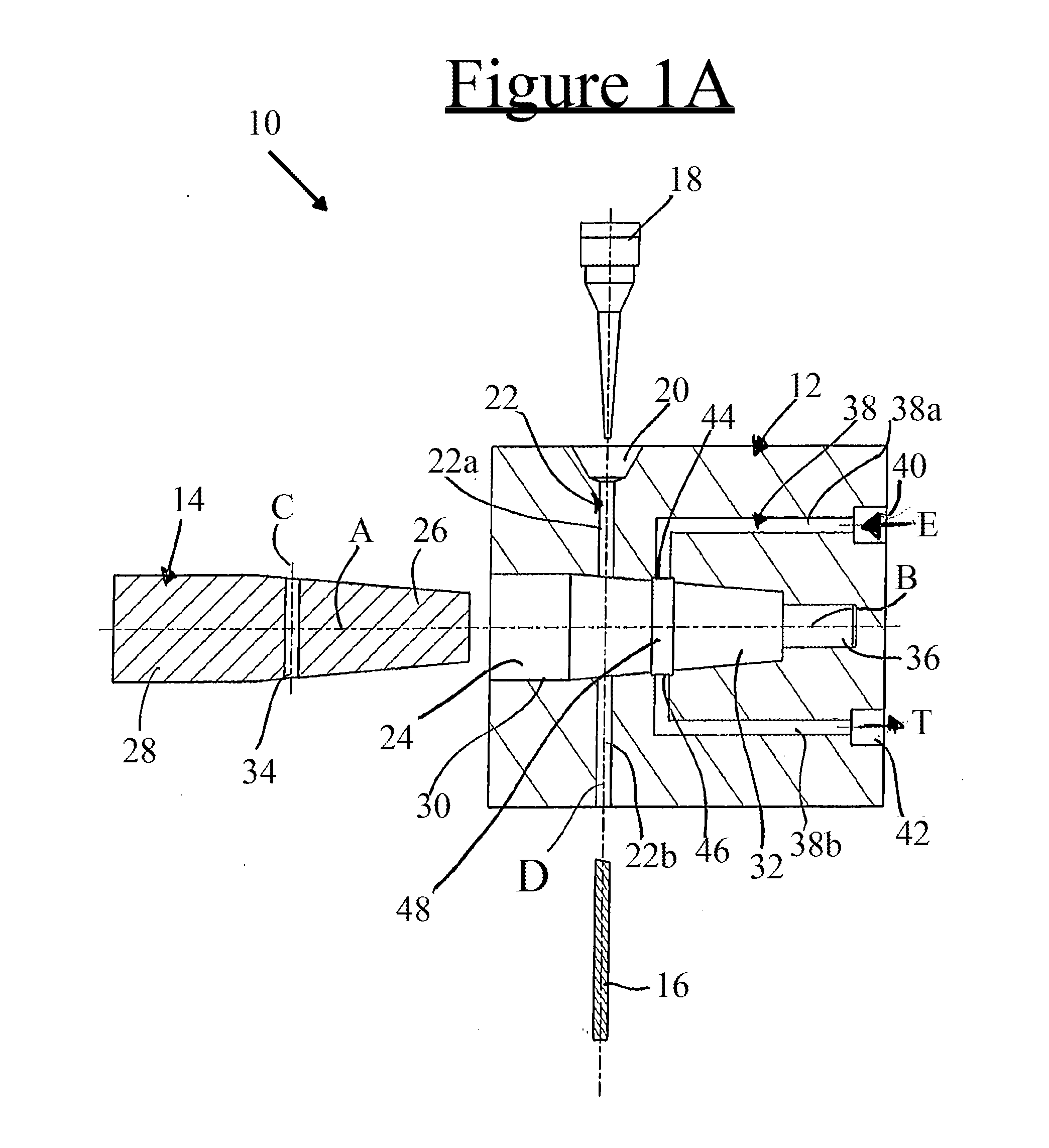
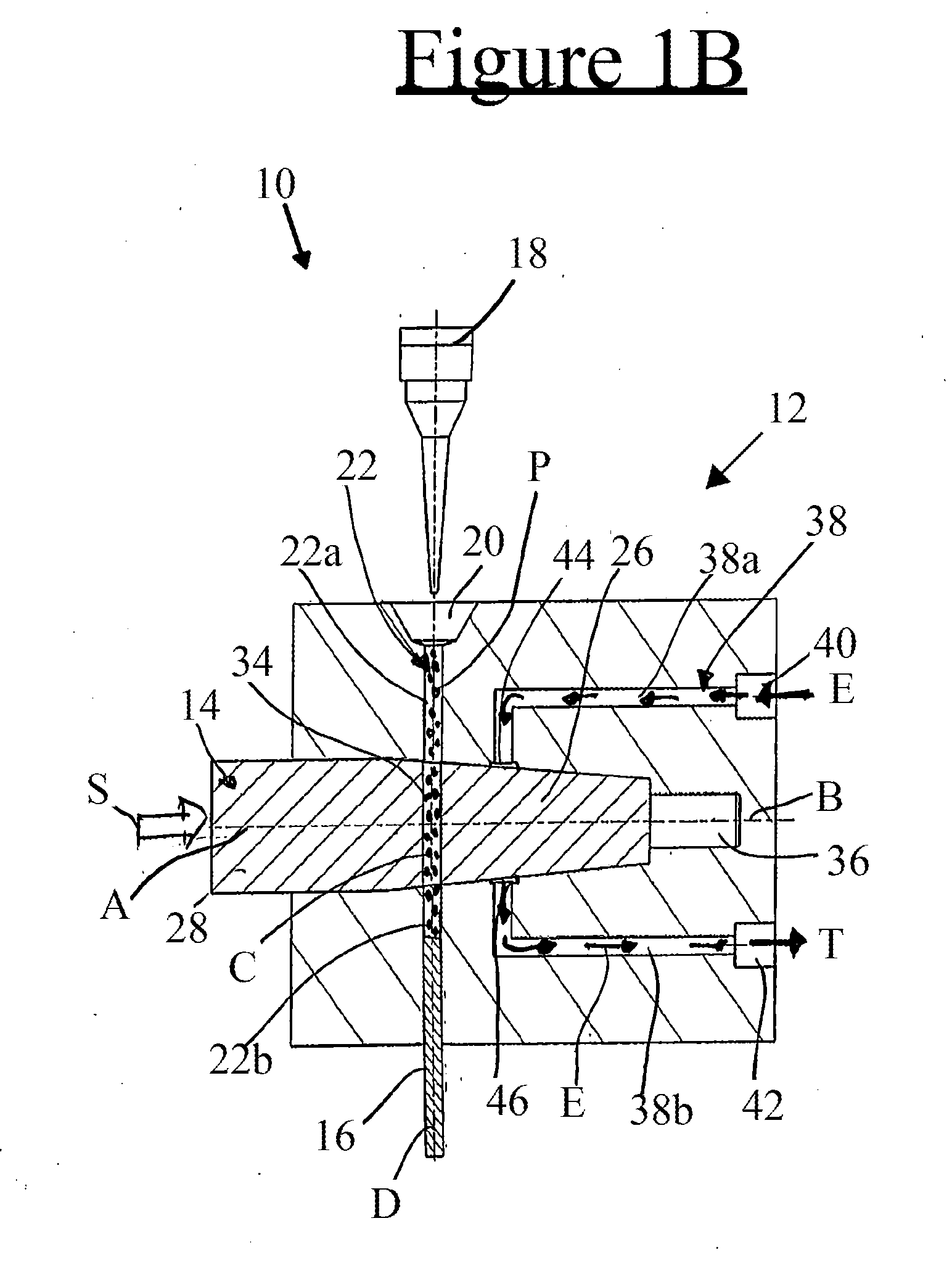
[0055]FIG. 1A shows a simplified schematic illustration of a sample dispenser 10 according to the invention. The individual components are in FIG. 1A shown in an exploded view in a state prior to final assembly. The sample dispenser 10 comprises a valve body 12, an actuator 14 and a plug 16. Furthermore, FIG. 1A schematically indicates at 18 a pipette tip, which can be inserted into a pipette seat designated by 20, which is formed in the valve body 12. The pipette tip 18 contains a sample to be analyzed, which can be coupled to the sample dispenser 10 by insertion into the pipette seat 20. For example, sample substance contained therein, in the embodiment shown in FIG. 1A in liquid form, can be inserted into a sample intake channel 22 formed in the valve body 12 by a corresponding operation of the pipette tip 18. It is also conceivable to provide a coupling mechanism which, when inserting the pipette tip 18 into the pipette 20, feeds the substance to be analyzed from the pipette tip...
second embodiment
[0073]FIG. 2A shows a simplified schematic illustration of a sample dispenser 10 according to the invention in the intake position. As mentioned above, only the differences compared to the embodiment shown in FIG. 1A to 1C will now be described, while regarding the remaining details, reference is made to the respective embodiment in FIGS. 1A to 1C. The embodiment according to FIG. 2A to 2C differs from the embodiment according to FIG. 1A to 1C only in that the eluent stream passes, in the intake position (FIG. 2A), between the orifice 44 of the upper flow channel section 38a opening into the cavity 24 and the orifice 46 of the lower flow channel section 38b opening into the cavity 24, through a further transverse channel 50 formed in the actuator 14. The transverse channel 50 is, in the intake position, aligned flush with the orifices 44, 46 such that the eluent passage is formed by the upper flow channel section 38a of the valve body 12, the other transverse channel 50 of the actua...
fourth embodiment
[0083]FIG. 4 shows a simplified schematic illustration of a sample dispenser 10 according to the invention. As mentioned above, only the differences compared to the previously described embodiments are described, while regarding the remaining details, reference is made to the respective embodiments mentioned above. The sample dispenser 10 shown in FIG. 4 comprises a plurality of actuators 14A, 14B, 14C, 14D. Each of the actuators 14A, 14B, 14C, 14D is associated with a respective injection valve arrangement. Each injection valve arrangement also comprises a valve body 12A, 12B, 12C, 12D and a valve seat 20A, 20B, 20C, 20D. Each valve seat 20A, 20B, 20C, 20D is associated with a pipette tip 18A, 18B, 18C, 18D. The injection valve arrangements according to FIG. 4 may be constructed in accordance with any of the embodiments described above. In the situation shown in FIG. 4, the actuator 14A of the first injection valve is positioned in the intake position and the other actuators 14B, 1...
PUM
| Property | Measurement | Unit |
|---|---|---|
| angle | aaaaa | aaaaa |
| angle | aaaaa | aaaaa |
| angle | aaaaa | aaaaa |
Abstract
Description
Claims
Application Information
 - R&D
- Intellectual Property
- Life Sciences
- Materials
- Tech Scout
- Unparalleled Data Quality
- Higher Quality Content
- 60% Fewer Hallucinations
Browse by: Latest US Patents, China's latest patents, Technical Efficacy Thesaurus, Application Domain, Technology Topic, Popular Technical Reports.
© 2025 PatSnap. All rights reserved.Legal|Privacy policy|Modern Slavery Act Transparency Statement|Sitemap|About US| Contact US: help@patsnap.com


