Electrical motor system and method of operating the electrical motor system

Active Publication Date: 2016-03-17
ARM LTD
View PDF12 Cites 31 Cited by
  • Summary
  • Abstract
  • Description
  • Claims
  • Application Information

AI Technical Summary

Benefits of technology

[0019]In some embodiments, the rotor teeth may be arranged such that when a first rotor tooth is closest to a stator tooth wound with the first coil of the set, further rotor teeth in positions adjacent-plus-one to the first rotor tooth provide the predominant return path for a magnetic field induced in the first rotor tooth. Thus the predominant return path for the magnetic field is relatively short—being via those further rotor teeth in adjacent-plus-one positions, and not for example further round the rotor. This enhances the magnetic field density in those regions where it is actively required to power the motor.
[0020]In some embodiments, the rotor teeth and the stator teeth may be arranged with respect to one another in a configuration in which, for any given relative orientation of the rotor section and the stator section, two of the set of six stator teeth may be substantially aligned (in other embodiments, a maximum of two) with corresponding rotor teeth, and wherein when the maximum of two of the set of six stator teeth are substantially aligned with corresponding rotor teeth no other stator teeth of the set of six stator teeth have at least partial alignment with corresponding rotor teeth. This configuration means that for the teeth which are aligned a configuration results in which there may be only a relatively small air gap between the rotor tooth and the stator tooth, corresponding to a low reluctance and hence no output power (zero torque) from the motor. Conversely the non-alignment of the other stator teeth of the set of six stator teeth with corresponding rotor teeth can thus provide a high reluctance and high torque configuration (due to the air gap between the non-aligned stator/rotor teeth). It will be appreciated that in some switched reluctance electric motors partial overlap between the rotor and stator teeth may be required in order to keep the motor in a configuration where torque can be achieved for an acceptable efficiency. However, the present electrical motor system achieves an improved trade-off between tor

Problems solved by technology

Some electric motors have been created with more phases, but a significant factor in creating such multi-phase electrical motors is the cost of the phase driver electronics.
In conventional motors a pulse width modulation (PWM) voltage controller (typically arranged with an H-bridge topology to drive motor coils bi-directionally) is coupled to a large power supply and the large voltages and currents which are required to drive the motor coils can add significantly to the cost of the driver circuitry.
Accordingly, multiple phase motors requiring multiple coil driver circuits are expensive to produce according to contemporary techniques.
Also conventional motors usually only operate at their h

Method used


Image

  • Electrical motor system and method of operating the electrical motor system
  • Electrical motor system and method of operating the electrical motor system
  • Electrical motor system and method of operating the electrical motor system

Examples


Embodiment Construction

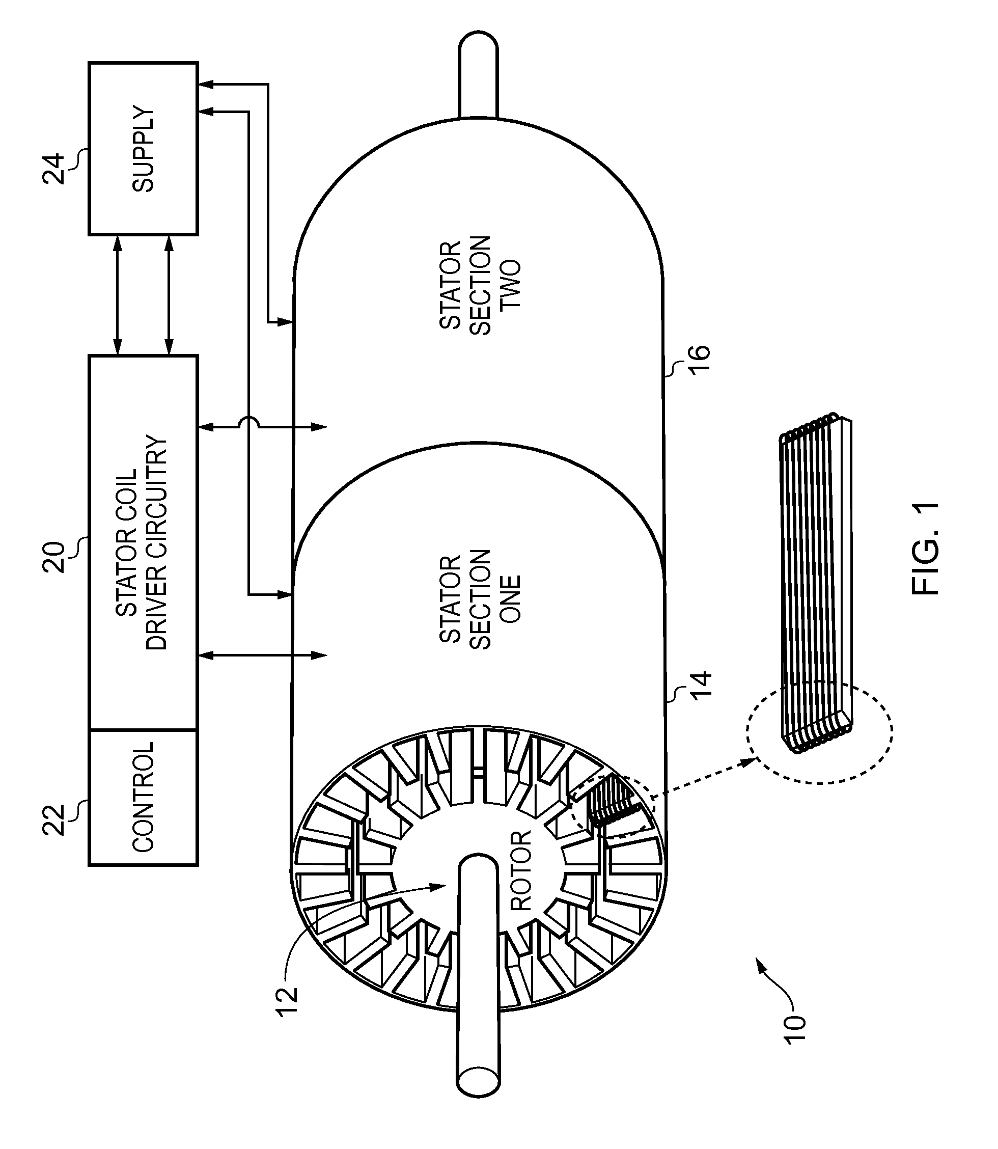
[0048]FIG. 1 schematically illustrates a switched reluctance electrical motor system 10 in one embodiment. The electrical motor comprises a rotor section 12 configured to rotate within two stator sections 14 and 16. The rotor section is configured to have sixteen rotor teeth, which form longitudinal spines extending radially outward and running along the length of the rotor section through both stator sections 14 and 16. Each stator section is configured to have twenty four stator teeth, which form longitudinal spines extending inwardly and also running along the length of each stator section. Each stator tooth is wound with a coil comprising a high number of turns—in this instance there being approximately two hundred. In the embodiment illustrated in FIG. 1 there are no coils on the rotor teeth, as the magnetic fields generated by powering the stator teeth coils cause the motor to rotate by the action of those magnetic fields on the rotor.

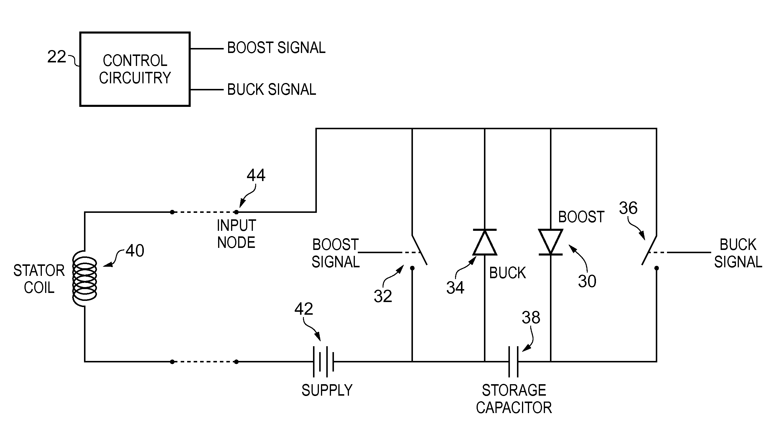
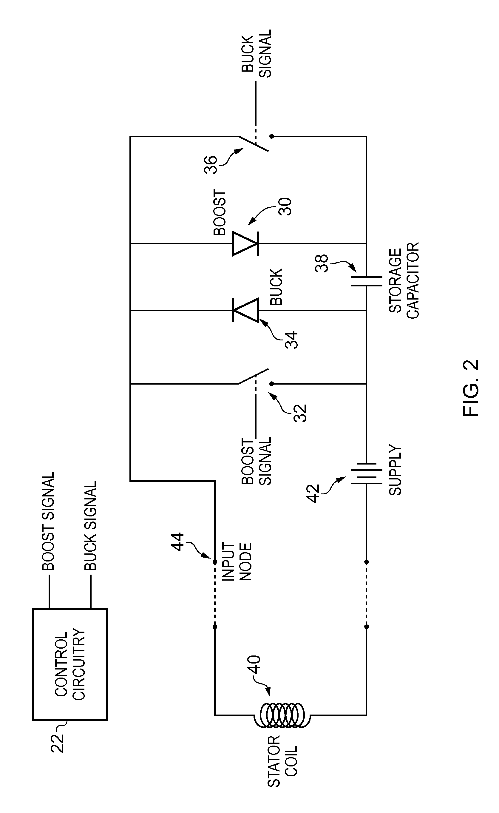
[0049]The electrical motor system 10 furth...


PUM


Abstract

An electrical motor system comprises a switched reluctance electrical motor comprising a rotor section and a stator section, the rotor section comprising a plurality of rotor teeth and the stator section comprising a plurality of stator teeth, the stator teeth wound with respective coils. Coil driver circuitry is coupled to the coils of the stator teeth and controls an independent phase of electrical power to each coil of the plurality of stator teeth. The coils of the stator teeth each have an inductance which absorbs electrical energy provided to that coil by the coil driver circuitry and subsequently releases at least a portion of the electrical energy back to the coil driver circuitry when that coil is not being actively driven by the coil driver circuitry. The coil driver circuitry comprises an electrical energy store configured to store the portion of the electrical energy released back from the inductance of each coil and the electrical energy provided to each coil of the stator teeth by the coil driver circuitry is augmented by the electrical energy stored in the electrical energy store.

Description

TECHNICAL FIELD[0001]The present disclosure relates to an electrical motor system. More particularly, this disclosure relates to an electrical motor system comprising a switched reluctance electrical motor.DESCRIPTION OF THE PRIOR ART[0002]In an electrical motor which has coil windings as part of its stator, such as in a switched reluctance electrical motor, it is common for the electrical motor to be powered by a three phase power supply and to apply AC waveforms to the coil windings to control the operation of the motor. Some electric motors have been created with more phases, but a significant factor in creating such multi-phase electrical motors is the cost of the phase driver electronics. In conventional motors a pulse width modulation (PWM) voltage controller (typically arranged with an H-bridge topology to drive motor coils bi-directionally) is coupled to a large power supply and the large voltages and currents which are required to drive the motor coils can add significantly...

Claims


Application Information

Patent Timeline
IPC IPC(8): H02P6/14
CPCH02P6/14H02K3/18H02K11/22H02K16/00H02K19/103H02K2213/03H02K2213/12H02P25/092
Inventor PIETROMONACO, DAVID
Owner ARM LTD
Why Eureka
Try Eureka