Cutting blade for oscillating tool

a cutting blade and oscillating technology, applied in the direction of power driven reciprocating saws, metal working devices, manufacturing tools, etc., can solve the problem of not being functionally wider than the front end

Active Publication Date: 2016-03-24
WORKTOOLS
View PDF38 Cites 18 Cited by
  • Summary
  • Abstract
  • Description
  • Claims
  • Application Information

AI Technical Summary

Benefits of technology

[0011]If the blade is held near the rear portion of the front element and / or it is moved slowly in and out, a smooth sideways cutting action is possible, in particular in panel type materials such as plywood, although widening is also possible in thicker materials. An initial slot can thereby be widened. This is not possible with a conventional rectangular toothed blade.

Problems solved by technology

In particular, the front end is not functionally wider than the rearward portions.

Method used


Image

  • Cutting blade for oscillating tool
  • Cutting blade for oscillating tool
  • Cutting blade for oscillating tool

Examples


Embodiment Construction

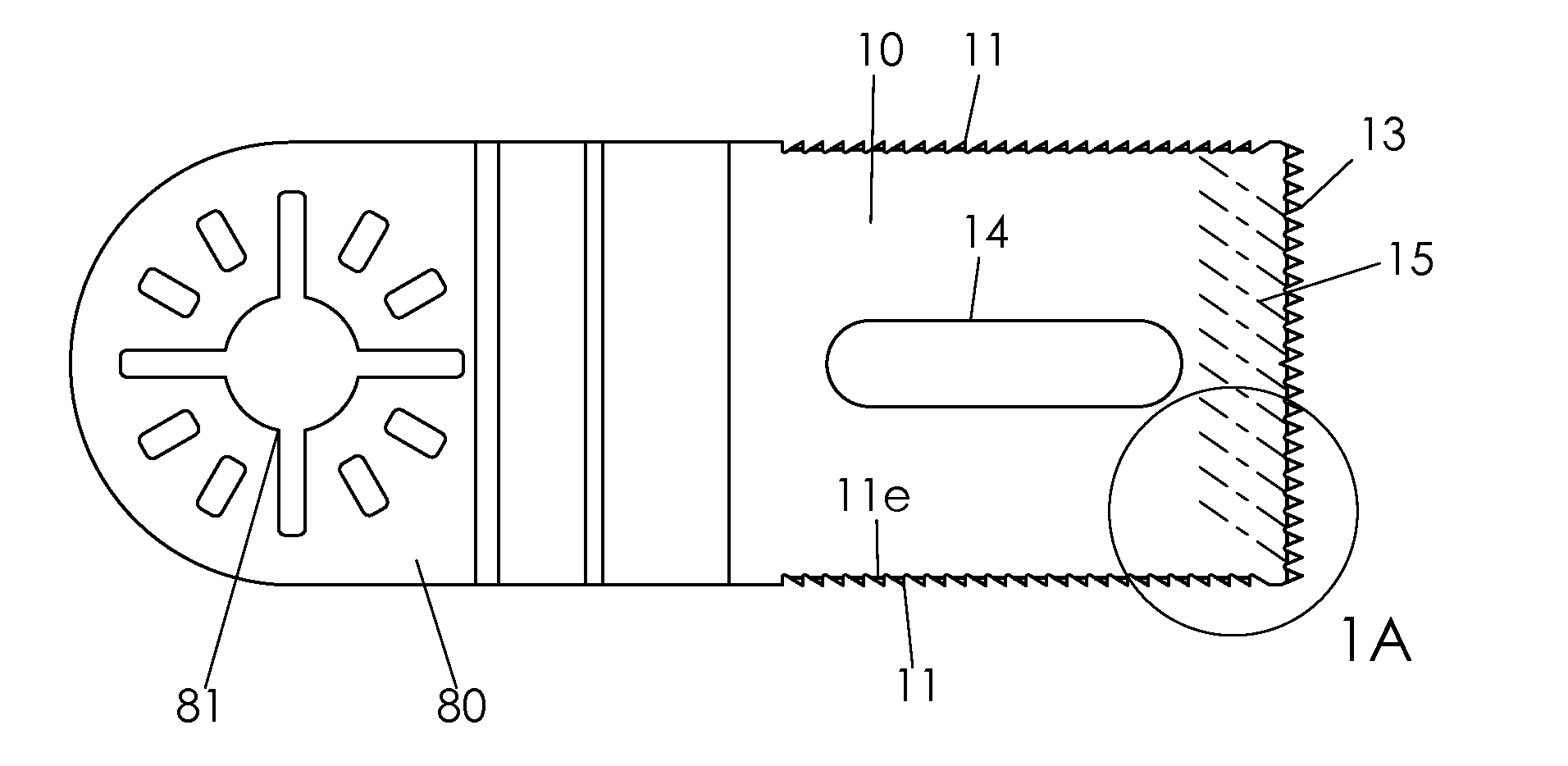
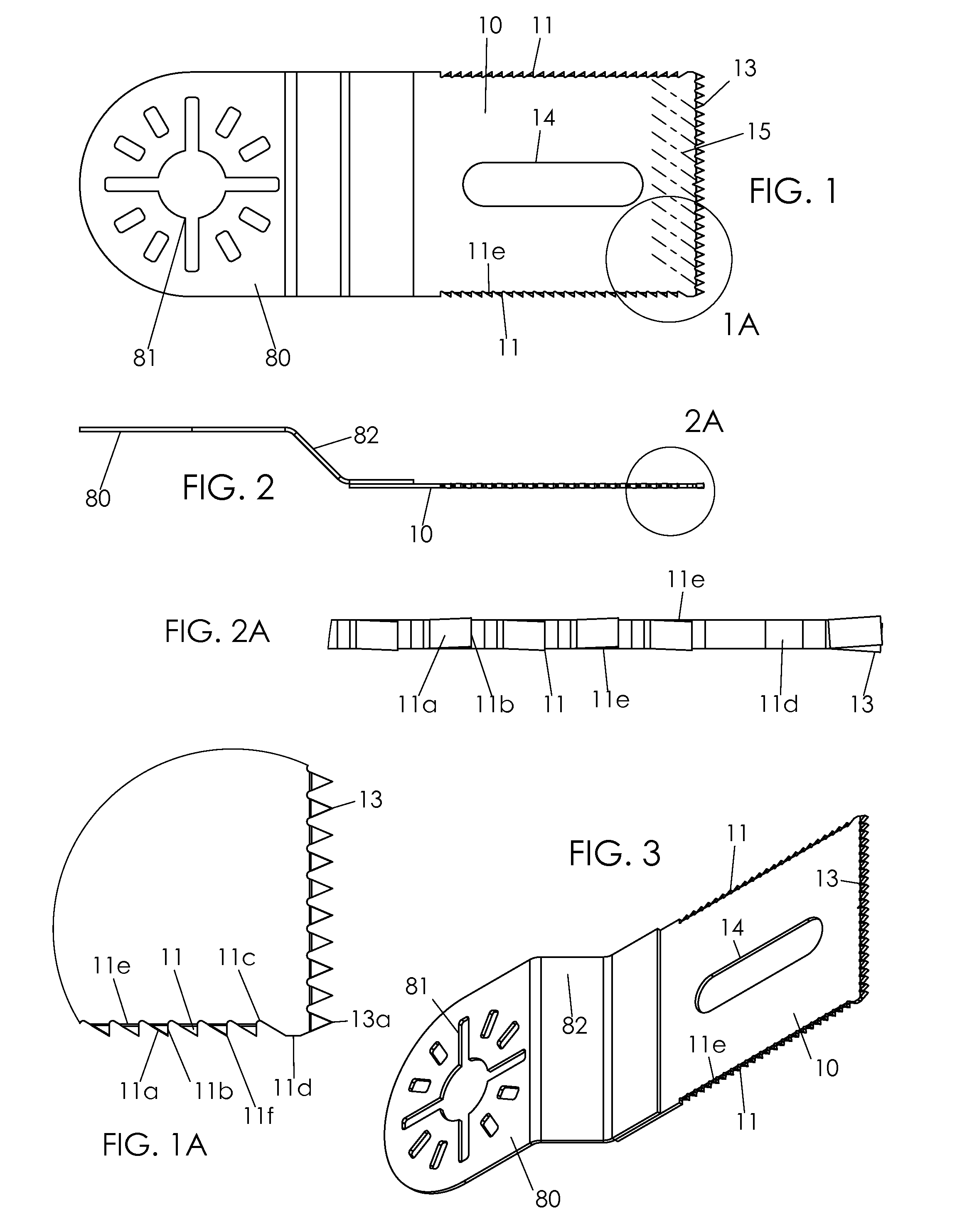
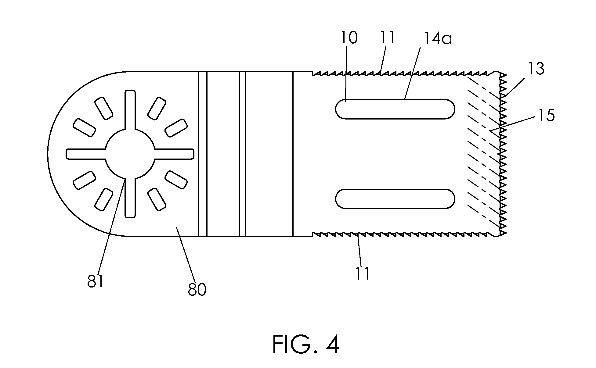
[0018]FIGS. 1 to 3 show an oscillating tool blade according to a preferred embodiment of the invention. Rear mount 80 is at a rear length of the tool blade. Mount 80 includes openings 81 or equivalent structures to fit upon an oscillating power tool head. These features are often configured to fit multiple brands of such tools. The power tool, not shown, is typically hand held and provides an oscillating motion to the blade, rotating about the circular opening of 81 and thereby up and down at the right front end in FIG. 1. Segment 82 often is angled to hold the working element 10 out of plane from the rear mount and may be considered a portion of the rear mount. A solution is desired for practical blind plunge cuts with an oscillating tool that provides reduce stress and a slot widening ability.

[0019]Cutting teeth 13 are typically cut into the distal end of working end or front element 10 as shown. As best seen in FIG. 2, mounting end 81 and working end 10 are joined at a two layer ...


PUM


Abstract

An improved blade for use with an oscillating power tool is disclosed. A rectangular style blade includes side teeth to eject debris and allow rapid but well controlled blind plunge cuts. The side teeth are preferably asymmetric with a forward orientation to bias debris out and the blade inward. Preferably one or more openings or slots allow for additional debris removal. The side teeth also allow for controlled side cutting.

Description

CROSS-REFERENCE TO RELATED APPLICATIONS[0001]This non-provisional application claims benefit of priority from U.S. provisional application no. 62 / 053,576, filed on Sep. 22, 2014, the contents of which are hereby incorporated by reference.FIELD OF THE INVENTION[0002]The present invention relates to oscillating power tool cutting blades. More precisely the present invention includes improvements to a toothed such blade.BACKGROUND OF THE INVENTION[0003]Oscillating power tools employ side to side vibratory motion to cut or work upon materials. A rear mount of the blade removably attaches to a head of the power tool. A working front element of the blade is further attached to the rear mount portion, typically permanently. In one common configuration, the working end is of sheet metal or similar flat form including a toothed front end. This blade moves against a work piece to cut into the piece. Such blade most often is of elongated rectangular shape with straight edged sides and teeth di...

Claims


Application Information

Patent Timeline
Patent Type & Authority Applications(United States)
IPC IPC(8): B26B7/00B26D7/08B27B19/00
CPCB26B7/00B26D7/086B27B19/008B26D1/30B26D2001/006
Inventor MARKS, JOEL, S.
Owner WORKTOOLS
Why Eureka
Try Eureka