Laterally moving shade roller tube

a roller tube and shade technology, applied in the field of roller shades, can solve the problems of not being able to fully cover the window at various heights, the trapezoidal roller shade design is not well-suited for such upper limit or lateral position adjustment, and the shade cannot be fully lifted withou

Active Publication Date: 2016-03-24
AUTO MOTION SHADE
View PDF5 Cites 14 Cited by
  • Summary
  • Abstract
  • Description
  • Claims
  • Application Information

AI Technical Summary

Benefits of technology

[0011]In one embodiment, the present invention facilitates adjusting at least one of the starting axial position of the roller tube on the support tube and optionally also the maximum distance of upward travel of the bottom end of the shade by dispensing with the need for a spindle nut and redesigning the spindle to r...

Problems solved by technology

However, even with a shade of matching shape, without being able to move laterally, the shade would not fully cover the window at various heights over the range of vertical movement of the shade.
For example, if the roller tube did not move laterally there would either be a gap in coverage near at the corner of the window immediately adjacent the windshield or the shade could not be lifted fully without running up against the windshield.
Existing trapezoidal roller shade designs are not well-suited for such upper limit or lateral position adjustments.
This makes it difficult to adjust upper limit of movement of the bottom end of the shade without disassembling the roller shade assem...

Method used


Image

  • Laterally  moving shade roller tube
  • Laterally  moving shade roller tube
  • Laterally  moving shade roller tube

Examples


Embodiment Construction

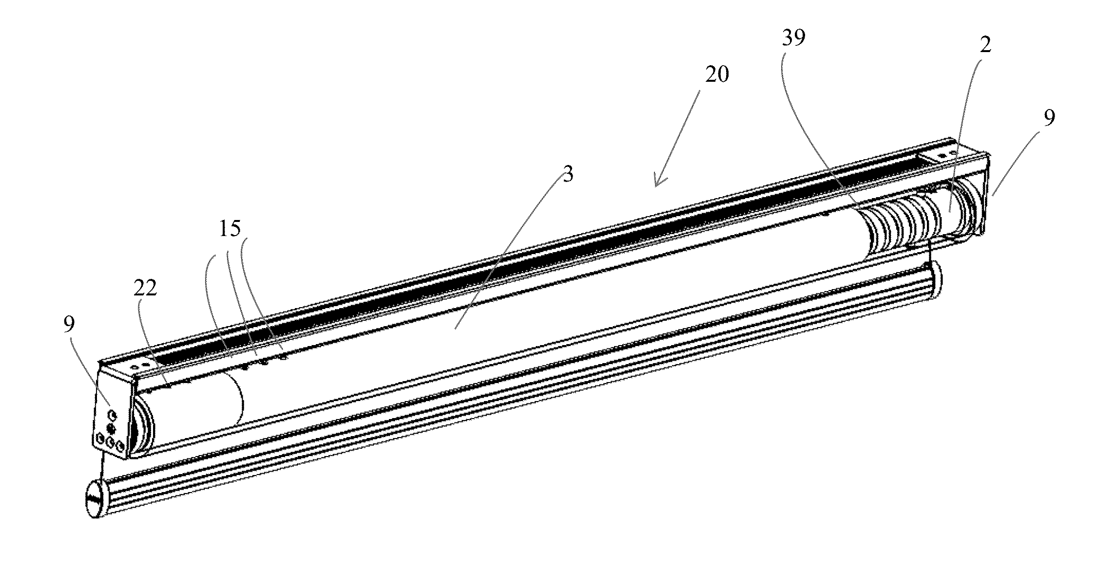
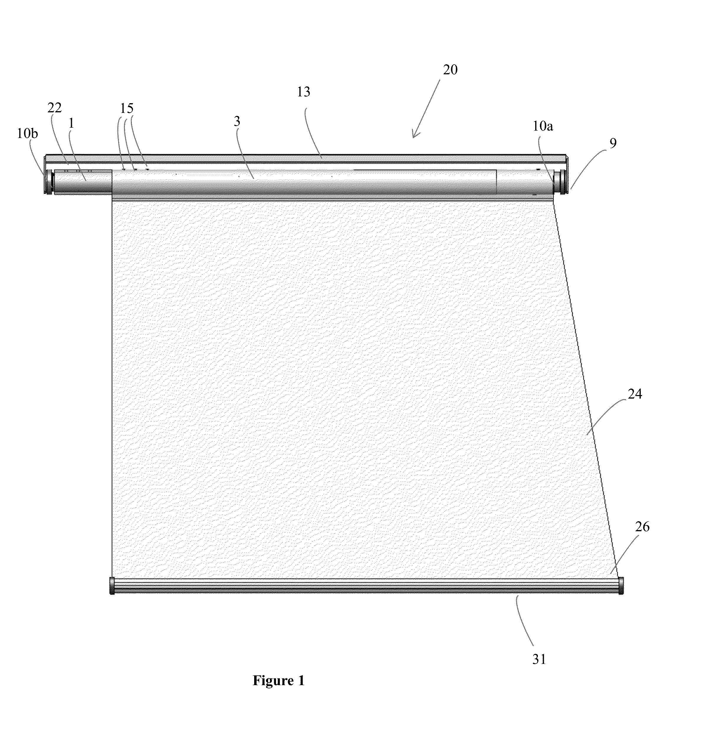
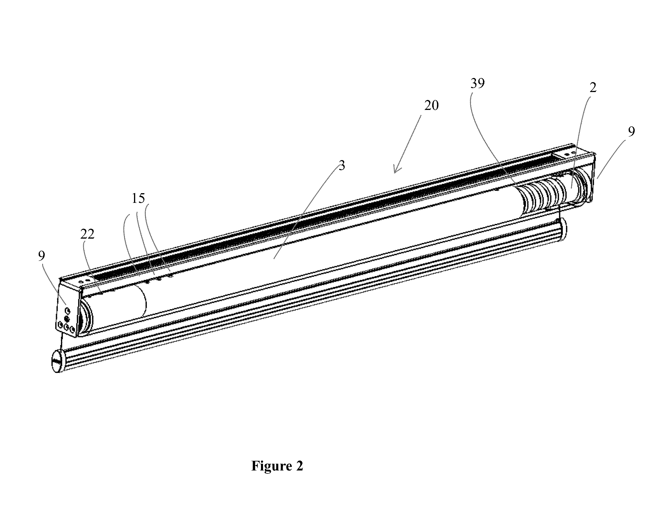
[0071]The term “axial” means along an axis running over the length of the roller tube, support tube and / or spindle. These elements are arranged “longitudinally” i.e. along the length of the assembly between the two end faces of mounting brackets located at either end of the assembly. The term “axial rotation” is used to refer to rotation of a particular component about its axis whereas the term “axial” in the context of axial movement or travel is used to refer travel along the axis of the roller shade assembly and in particular along the axis of the co-axially aligned roller tube and support tube. Thus the roller shade, support tube, the adjustment wheel as well as other parts of the support shaft assembly are described as rotating “axially”, whereas the roller tube is also described as moving “axially” i.e. laterally over the support tube; and the interiorly threaded axially driven element is described as moving or driven to travel axially, by rotation of the threaded shaft.

[0072]...


PUM


Abstract

A roller shade assembly comprising a roller tube having an inner surface defining an axial bore, a spindle including an outer threaded portion defining a helical groove, the spindle configured to be received in the axial bore of the roller tube for axial movement in the roller tube at one end roller tube and at least one tracking element operatively associated with the roller tube, the at least one tracking element configured for riding in the helical groove to convert axial rotation of roller tube into axial movement of the roller tube on the support tube. The tracking element engages the helical groove from a position more proximal to one end of the roller tube. The starting axial position of the roller tube in relation to the support tube is configured to be adjustable by manually rotating the spindle without rotating the support tube.

Description

FIELD OF THE INVENTION[0001]The present invention relates to roller shades and in particular to a roller shade assembly adapted to provide for lateral movement of the shade for the purpose of covering an irregular shaped window, for example a window of the type that may be found in recreational and other vehicles.BACKGROUND OF THE INVENTION[0002]Recreational and other vehicles are sometimes outfitted with irregular shaped windows, for example trapezoidal windows. Existing roller shades for trapezoidal windows are designed to enable the roller tube on which the shade is wound to move laterally over a support tube so that the shade can move laterally with the roller tube to fully cover the bottom of the window. For example, lateral movement of the roller tube may be particularly important when the shade is designed to occupy a confined space such as when the trapezoidal window is at the front of a vehicle, where it may be adjacent and orthogonal to an angled windshield. The shade may ...

Claims


Application Information

Patent Timeline
IPC IPC(8): E06B9/44B60J1/20
CPCB60J1/2066E06B9/44B60J1/205B60J1/2086E06B9/50
Inventor GRUTZNER, HANS
Owner AUTO MOTION SHADE
Why Eureka
Try Eureka