Projection device

a projection device and projection technology, applied in the direction of picture reproducers, picture reproducers using projection devices, instruments, etc., can solve the problems of large amount of parasitic light, large amount of light loss in micro-lens arrays, and light beam diffracted,

Active Publication Date: 2016-03-24
GOOGLE LLC
View PDF2 Cites 51 Cited by
  • Summary
  • Abstract
  • Description
  • Claims
  • Application Information

AI Technical Summary

Benefits of technology

[0052]As the MEMS micro mirror oscillates about a single oscillation axis, the focus point of the light reflected by the MEMS micro mirror will be moved over a curve (i.e. an arc). To ensure that the light beams are always focused at the surface of the convex reflective projections in the reflective element, as the MEMS micro mirror oscillated about its oscillation axis, the convex reflective projections are arranged to lie on a curved plane whose curvature is equal to the curvature of the curve over which the focus point of the light reflected by the MEMS micro mirror is moved when the MEMS micro mirror is oscillated about its single oscillation axis. In this manner the reflective element can compensate for changes in the position of focus point of light reflected by the MEMS micro mirror, which occurs when the MEMS micro mirror oscillates. Thus, the convex reflective projections of the reflective element are located at the focus length of the light reflected by the MEMS micro mirror, even as the MEMS mirror oscillates about its single oscillation axis.
[0053]Likewise the MEMS micro mirror may be oscillated about two orthogonal oscillation axes. In such a case it may be preferable to arrange the convex reflective projections of the reflective element to lie on a spherical plane, or on an aspherical plane. The curvature of spherical plane, or aspherical plane, is preferably such that it corresponds to the curvature of a plane over which the focus point of the light reflected by the MEMS micro mirror moves as the MEMS mirror oscillates about these two orthogonal oscillation axes. Thus in this manner the reflective element can compensate for changes in the position of focus point of light reflected by the MEMS micro mirror, which occurs when the MEMS micro mirror oscillates about its two orthogonal oscillation axes. Thus, the convex reflective projections of the reflective element are located at the focus length of the light reflected by the MEMS micro mirror, even as the MEMS mirror oscillates about its two orthogonal oscillation axes.

Problems solved by technology

Disadvantageously when the light beams are transmitted through the micro-lenses in the micro-lens array the light beams are diffracted and large amounts of light loss will occur in the micro-lens array.
Furthermore, a large amount of parasitic light is created when the light beams are transmitted through the micro-lenses in the micro-lens array; this parasitic light creates speckle and / or visual parasitic patterns in the projected image as well as reducing the overall contrast between adjacent pixels.
The transparent holder portion thus further increases the amount of diffraction and light loss and also increases the amount of parasitic light which is created.
The transparent holder portion, as well as the transparent lenses, can further generate chromatic aberration.
Accordingly a projection device which uses any of the above-mentioned micro-lens arrays will be unable to project a high quality image due to the large amounts of diffraction, light loss, parasitic light, and chromatic aberration.
Moulds to manufacture such micro-lens arrays in high volume are very difficult to manufacture as the junctions between successive lens need to be pointed; if the junctions between successive lens are not pointed enough the junction will produce a lot of parasitic reflection during use which will decrease the quality of the projected image.
Thus it is difficult, and expensive, to produce high volume projection systems, which use micro-lens arrays which comprise an array of micro-lenses each of which have a reflective concave profile, and which can project a good quality image.
Furthermore a micro-lens array, which comprises an array of reflective micro-lenses each of which have a concave profile, will focus the light beams it receives; the focused light beams pose a risk to users as the focused light beams may possess enough light energy to damage a user's eyes or accidentally ignite dust particles (for example, dust particles found on car windshields or dust particles on the dashboard of a car, if such projection devices are used in a car).

Method used


Image

  • Projection device
  • Projection device
  • Projection device

Examples


Embodiment Construction

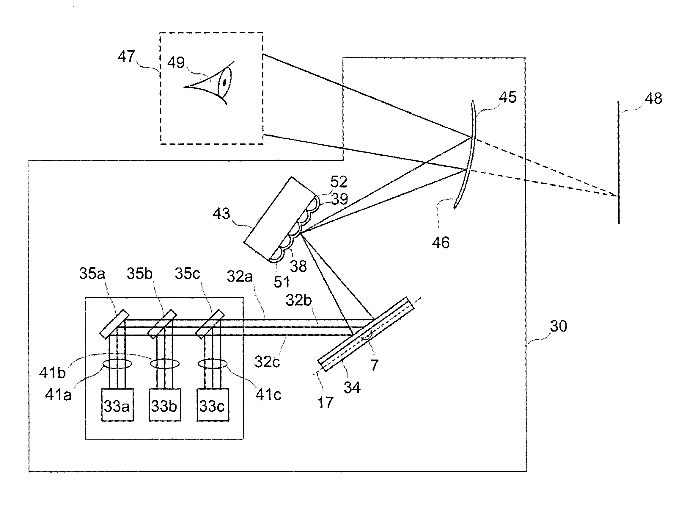
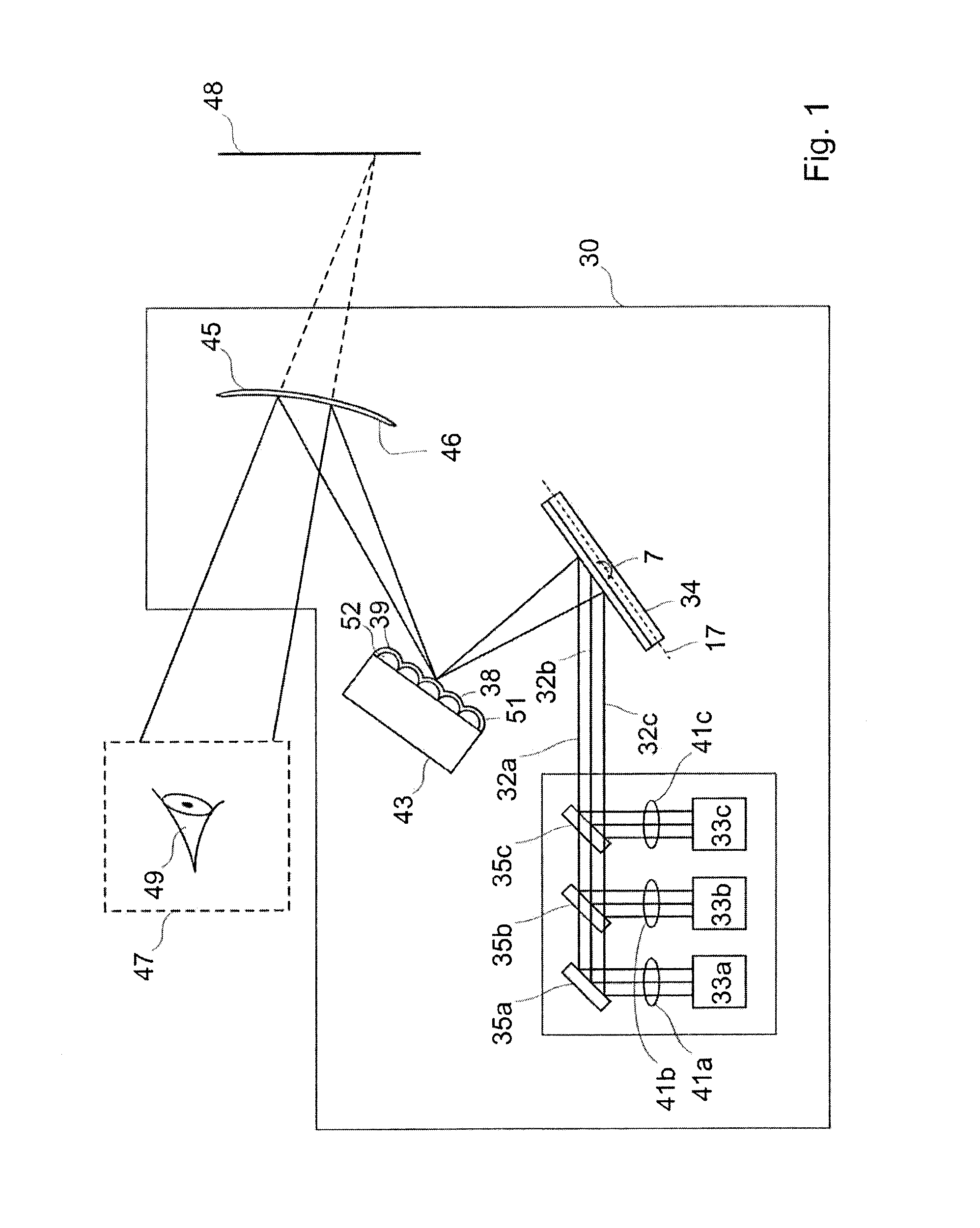
[0097]FIG. 1a is an aerial view of a projection device 30 according to an embodiment of the present invention.

[0098]The projection device 30 comprises a light source 31 which comprises red, green and blue light sources 33a,b,c which provide red, green and blue light beams 32a,b,c respectively. The red, green and blue light beams 32a,b,c, when combined, define one or more pixels of a virtual image 48 which is projected by the projection device 30.

[0099]The projection device 30 further comprises a MEMS micro mirror 34 which is arranged to receive the light beams 32a,b,c provided by the light source 31. In this particular example the light source 31 comprises reflectors 35a,b,c which direct the red, green and blue light beams 32a,b,c, respectively, to the MEMS micro mirror 34.

[0100]The MEMS micro mirror 34 can oscillate about at least one oscillation axis 7,17 to scan the light beams 32a,b,c. As will be described in more detail later the MEMS micro mirror 34 may be configured to oscill...


PUM


Abstract

According to the present invention there is provided a projection device (30,50,100) comprising, a light source (31,61) which can provide light beams (32a,b,c 62a,b,c), wherein the light beams (32a,b,c 62a,b,c) can be used to define one or more pixels of a virtual image (48); a MEMS micro mirror (34) which is arranged to receive the light beams (32a,b,c 62a,b,c) provided by the light source (31,61), and wherein the MEMS micro mirror (34) can oscillate about at least one oscillation axis (7,17) to scan the light beams (32a,b,c 62a,b,c); a reflective element (38), which comprises a plurality of convex reflective projections (39), and wherein the reflective element (38) is arranged so that light beams (32a,b,c 62a,b,c) reflected by the MEMS micro mirror (34) are incident on said convex reflective projections (39), so that the light beams (32a,b,c 62a,b,c) are reflected by the convex reflective projections (39); a beam combiner (45,81), wherein the beam combiner is arranged to receive the light beams (32a,b,c 62a,b,c) which are reflected by the convex reflective projections (39) wherein the beam combiner (45,81) is configured to at least partially reflect the light beams (32a,b,c 62a,b,c) which it receives so that the light beams (32a,b,c 62a,b,c) can form a virtual image (48) which is visible when viewed from within an eyebox (47). There is further provided a corresponding method of projecting a virtual image.

Description

FIELD OF THE INVENTION[0001]The present invention relates to a projection device and in particularly, but not exclusively, to a projection device which comprises a diffuser in the form of a reflective element which comprises a plurality of reflective convex projections which reflect light beams to a beam combiner to project a virtual image. There is further provided a corresponding method of projecting a virtual image.DESCRIPTION OF RELATED ART[0002]Most projection devices use a diffuser to reduce the occurrence of the speckle in the projected image.[0003]In most cases a micro-lens array is used as a diffuser. Typically the micro-lenses in a micro-lens array are convex lenses and are sized between 10 to 500 μm. The micro-lens arrays are transparent during operation; thus the light beams must be transmitted through the micro-lenses in the micro-lens array in order to be diffused. Disadvantageously when the light beams are transmitted through the micro-lenses in the micro-lens array t...

Claims


Application Information

Patent Timeline
Patent Type & Authority Applications(United States)
IPC IPC(8): G02B27/48G02B5/02G02B13/16G02B13/22G02B26/08G02B26/10G02B27/01G02B27/10H04N9/31
CPCG02B27/48H04N9/3129G02B26/0833G02B26/105G02B13/16G02B5/0284G02B5/0215G02B27/0101G02B13/22G02B27/10G02B5/0263G02B5/0294G02B2027/013
Inventor MASSON, JONATHANKILCHER, LUCIO
Owner GOOGLE LLC
Why Eureka
Try Eureka