Inspection apparatus

Active Publication Date: 2016-03-24
BRIDGESTONE CORP
View PDF5 Cites 6 Cited by
  • Summary
  • Abstract
  • Description
  • Claims
  • Application Information

AI Technical Summary

Benefits of technology

The invention is an inspection apparatus that can accurately match a model pattern to an image of an inspection object, even if the image is captured with deformity. This prevents the inspection object from being incorrectly judged as nonconforming. The apparatus uses a model pattern positioning system, a model pattern dividing system, and a shape recognition system to perform pattern matching.

Problems solved by technology

However, in such an inspection, some products, which are in fact conforming units, may show low degrees of agreement between the image pattern of the inspection object and the model pattern.
Tires before such inspection are placed in a certain location temporarily, and, as a result, the sides of tires can get deformed by the sagging of the rubber or the overlap of belts.

Method used


Image

  • Inspection apparatus
  • Inspection apparatus
  • Inspection apparatus

Examples


first embodiment

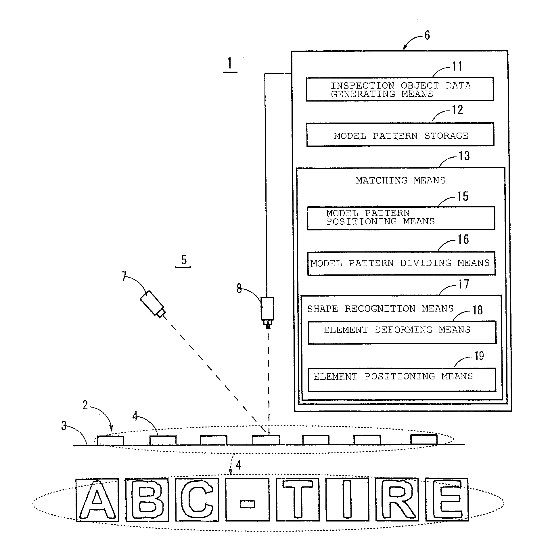
[0011]FIG. 1 is a schematic configuration diagram of an inspection apparatus 1 for a tire 2 implementing an embodiment of the present invention. As shown in FIG. 1, the inspection apparatus 1 according to the first embodiment is an apparatus for inspecting for acceptability each of molded characters, which constitute a character string 4 with protrusions and recesses molded on the side 3 of the tire 2. The tire 2 in this case is supposed to be one having a deformed side 3 because it has been placed after manufacture temporarily in a certain location before the inspection. The inspection apparatus 1 has an inspection object imaging unit 5 for capturing an image of the character string 4 on the side 3 of a “not inflated” tire 2 and a pattern matching unit 6.

[0012]The inspection object imaging unit 5 comprises a unit for capturing the whole image of the character string 4 by optical cutting method (light-section method), for instance. The unit consists of a laser unit 7 for emitting a ...

second embodiment

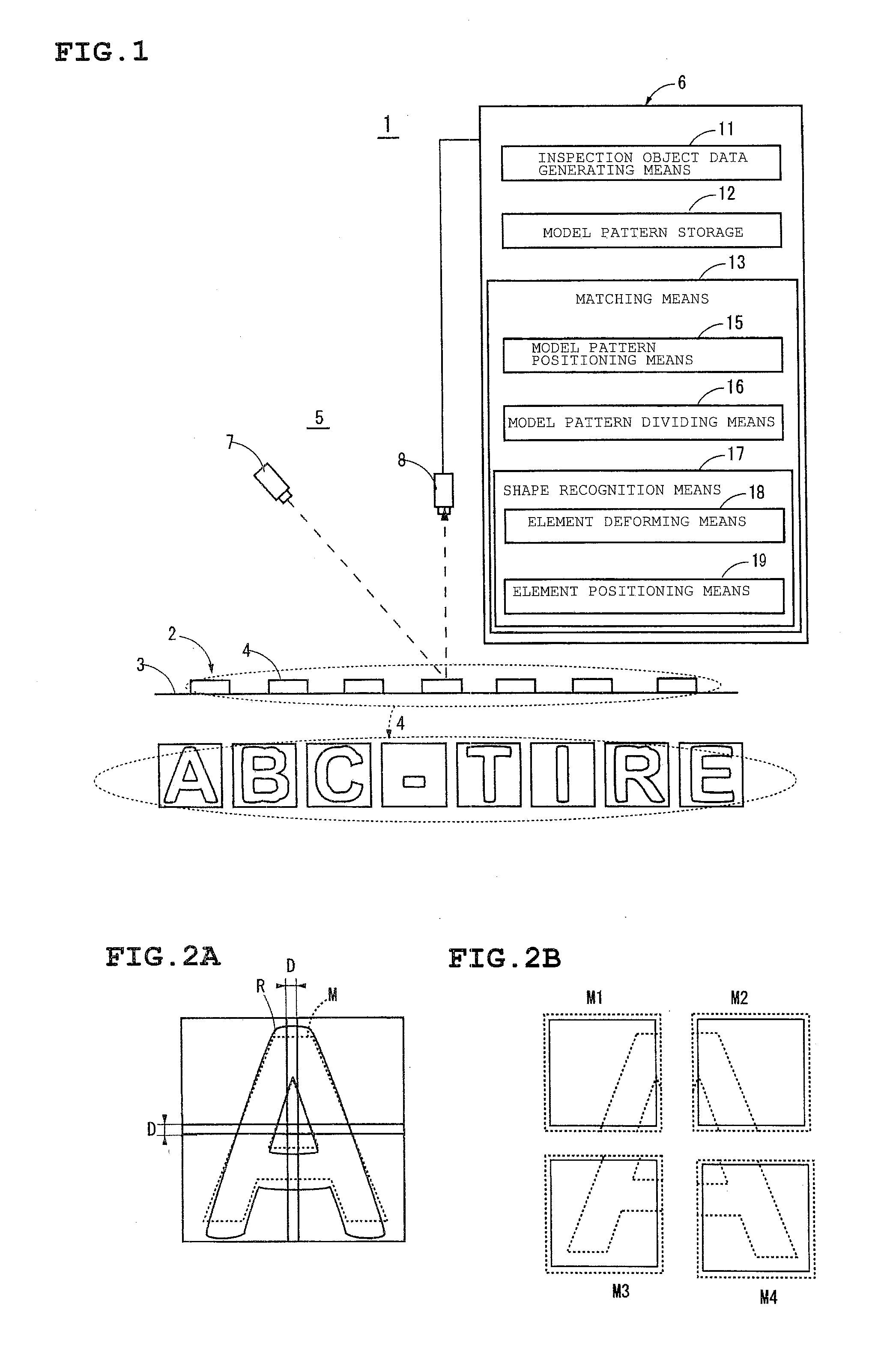
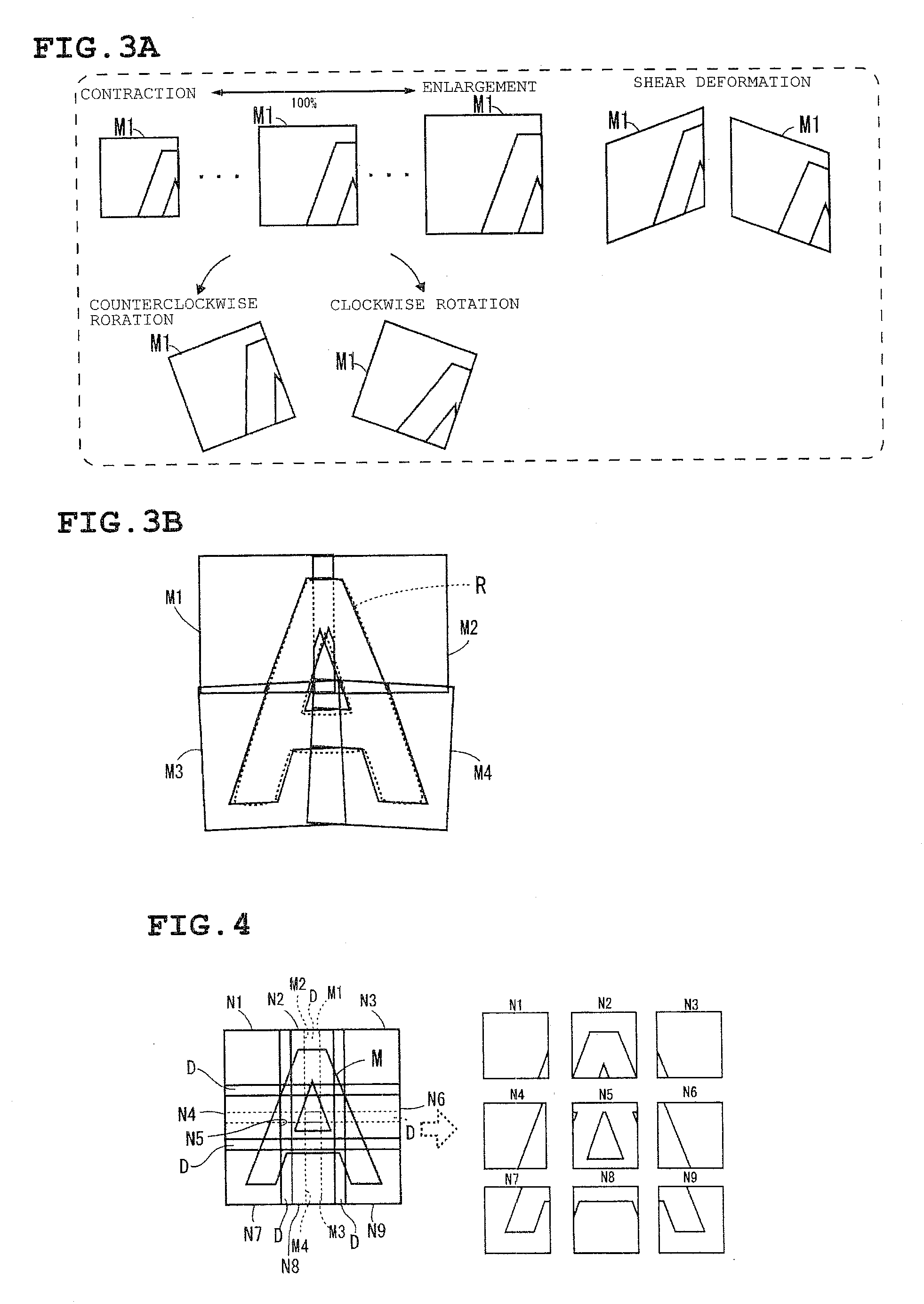
[0029]The first embodiment has been so described that the model pattern M is divided into 2×2 elements by the model pattern dividing means 16 as shown in FIG. 2A. However, the arrangement may be such that pattern matching against the image pattern R is performed by dividing the model pattern M into 3×3 elements N1 to N9 as shown in FIG. 4, in addition to the above number of divisions, in such a manner that the division boundaries do not coincide with those of 2×2 divisions. In other words, the model pattern dividing means 16 in the second embodiment divides the model pattern M into the elements M1 to M4 and the elements N1 to N9, which are different in size from each other. And the shape corresponding to the model pattern M is recognized by the shape recognition means 17 whenever the model pattern M is divided in a different size. In this case, the arrangement may be such that the shape recognized in the 2×2 size is superposed on the shape recognized in the 3×3 size and the shape re...


PUM


Abstract

An inspection apparatus capable of preventing a conforming article from being judged as nonconforming when inspecting a molded object for acceptability by performing image processing on an image captured of the inspection object. The apparatus includes a means for positioning a model pattern in a position with a highest degree of agreement by matching the model pattern against the image captured of the inspection object, a model pattern dividing means for dividing the model pattern into a plurality of elements in such a manner as to have mutually overlapping regions, and a shape recognition means for recognizing a shape corresponding to the model pattern by positioning each of the elements divided by the model pattern dividing means in a position with a highest degree of agreement by performing pattern matching within a predetermined range with reference to the position where the model pattern has been positioned on the image.

Description

TECHNICAL FIELD[0001]The present invention relates to an inspection apparatus capable of preventing a conforming article from being judged nonconforming when inspecting a molded product for acceptability by performing image processing on an image captured of the appearance of the inspection object.BACKGROUND ART[0002]An inspection apparatus known in the art determines the acceptability of an inspection object by storing conforming article data, as a model pattern, of the inspection object, such as molded characters on a product, and calculating the degree of agreement between the image pattern obtained of the inspection object and the model pattern (see Patent Document 1).[0003]However, in such an inspection, some products, which are in fact conforming units, may show low degrees of agreement between the image pattern of the inspection object and the model pattern. Such situations may sometimes lead to judgment of conforming articles as nonconforming. For example, let us assume an i...

Claims


Application Information

Patent Timeline
IPC IPC(8): G06T7/00G01B11/24G01N21/88G06V10/75
CPCG06T7/001G01N21/8851G01B11/24G06T7/0044G06K2009/4666G06K9/4604G06T7/0085G01N2201/12G06T2207/20112G06T7/0081G01N21/95607G06T2207/30108G06T7/74G06T7/11G06T7/13G06V10/757G06V10/75G06F18/22
Inventor FUJISAWA, YOSHITAKA
Owner BRIDGESTONE CORP
Why Eureka
Try Eureka